Steering motor

a steering motor and steering shaft technology, applied in electrical steering, mechanical energy handling, transportation and packaging, etc., can solve the problems of motor failure, serious damage to the steering motor, carbon brush and collector ring wear and damage, etc., to simplify the whole structure of the steering motor, reduce structural wear and damage, and simplify the effect of the oil passage structur

Active Publication Date: 2017-04-20
GUANGDONG HUACHAN RES INST OF INTELLIGENT TRANSPORTATION SYST CO LTD
View PDF0 Cites 4 Cited by
  • Summary
  • Abstract
  • Description
  • Claims
  • Application Information

AI Technical Summary

Benefits of technology

[0027]Compared with the prior art, the steering motor provided by the present application utilizes a combined design of oil passages therein, and simplifies the whole structure of the steering motor by simplifying oil passage structure; furthermore, the steering motor is further provided therein with a cylinder assembly, the cylinder assembly utilizes an elastic oil bag, which reduces structural wear and damage caused by friction during a damping process, thereby prolonging the service life of the steering motor and saving cost.

Problems solved by technology

When the automobile does not veer, the electronic control unit will not send any instruction to the motor controller, and the motor does not work.
A traditional damping system generally utilizes a carbon brush and a collector ring; when the steering motor suffers shocks, the damping system begins to work and constantly buffers the shocks, which makes the carbon brush and the collector ring be rubbed continuously, hence the carbon brush and the collector ring may be worn and damaged due to friction.
Furthermore, the carbon brush and the collector ring are sensitive to temperature, and are prone to damage because of temperature changes, such that the stability and service life of the steering motor are seriously affected.
Thus, the oil passages occupy too much space in the steering motor, such that the structure of the steering motor is complex, which not only wastes resources but also increases manufacturing cost.

Method used


Image

  • Steering motor
  • Steering motor
  • Steering motor

Examples


Embodiment Construction

[0034]In order to make the purposes, technical solutions, and advantages of the present application more clear, the present application will be further described in detail hereinafter with reference to accompanying drawings and embodiments. It should be understood that the specific embodiments described herein are merely intended to explain but not to limit the present application.

[0035]The implementation of the present application will be described in detail hereinafter with reference to the following specific embodiments.

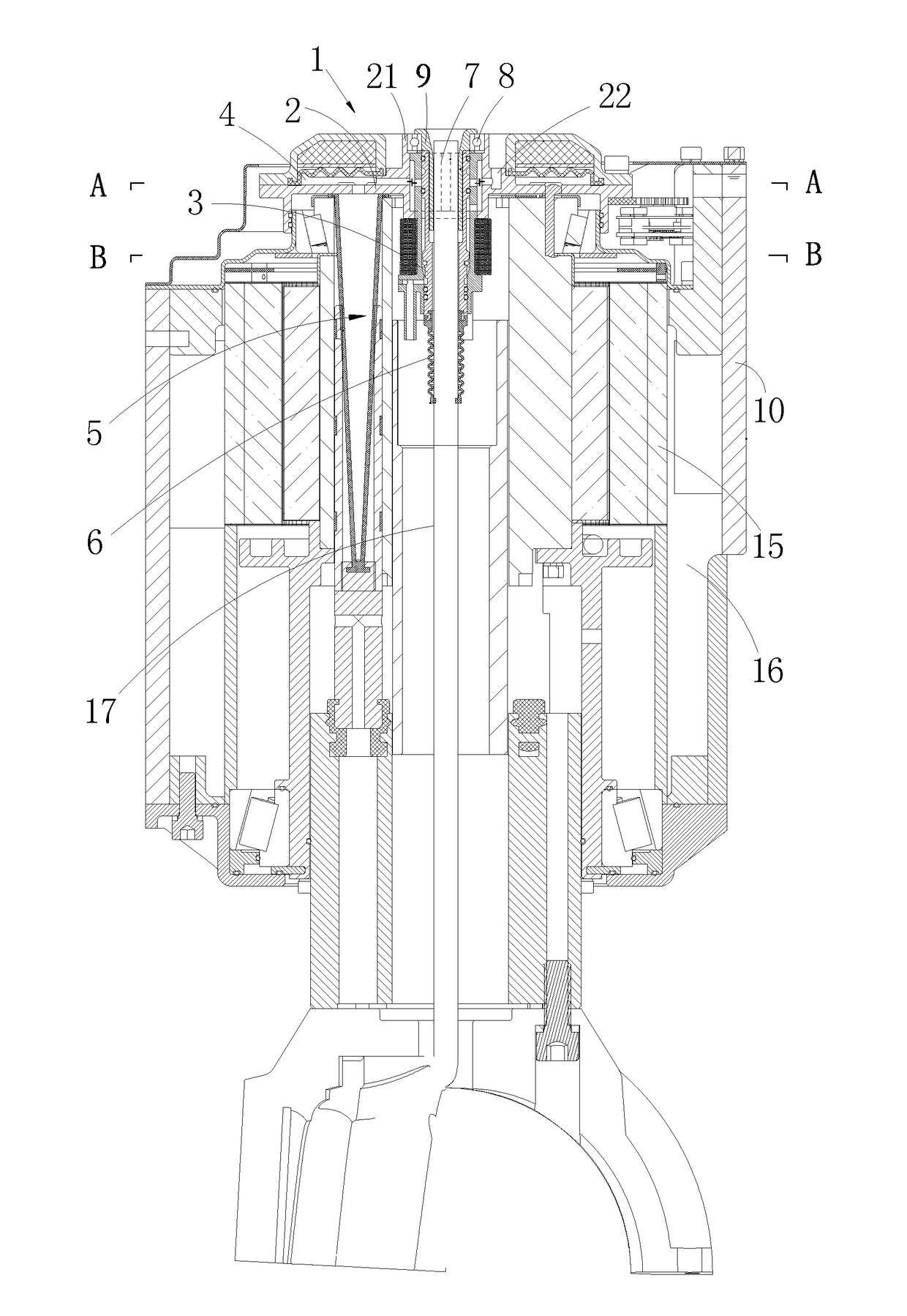
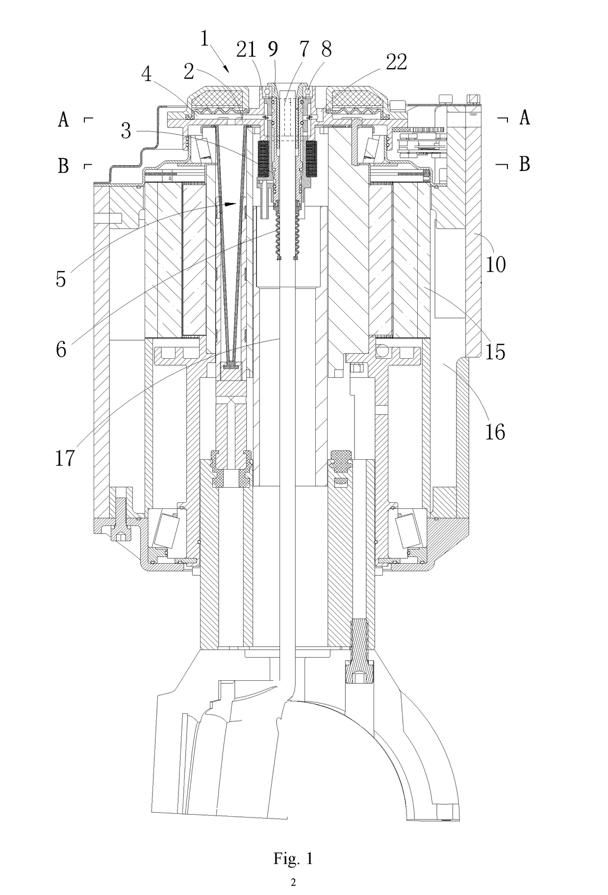
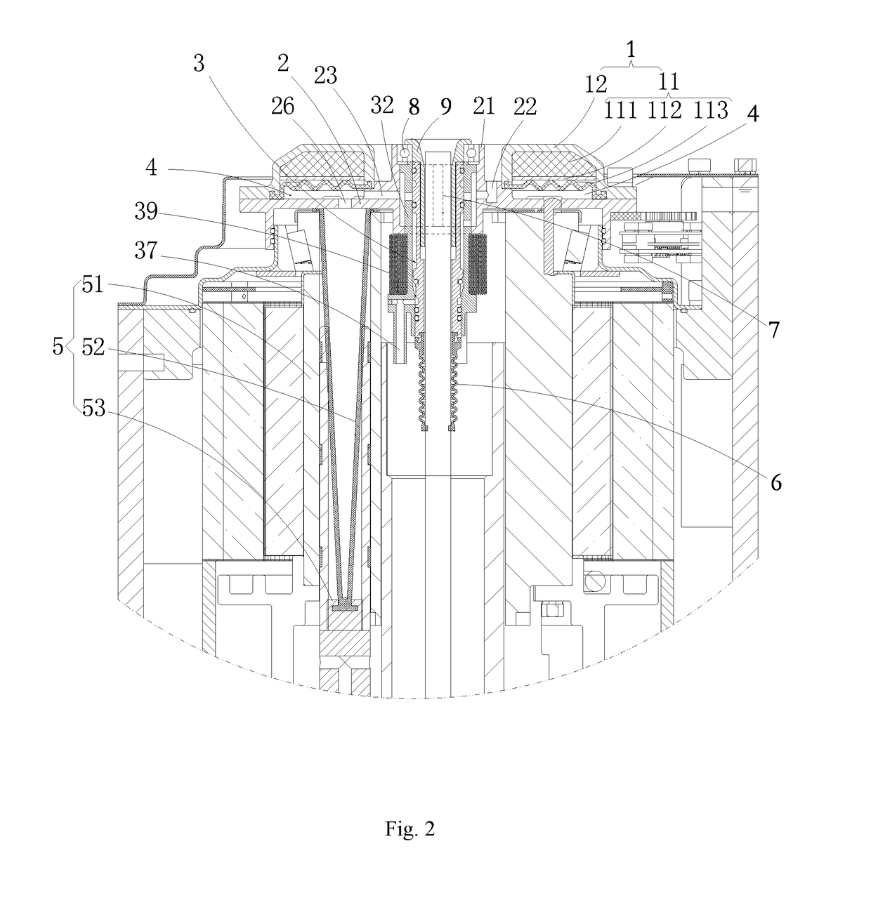
[0036]As shown in FIGS. 1-6, the present application provides a preferred embodiment.

[0037]The embodiment provides a steering motor, which includes a casing 10 with a cavity; a stator 15 is arranged in the cavity of the casing 10, and a chamber 16 is formed between an outer wall of the stator 15 and an inner wall of the casing 10.

[0038]The steering motor further includes an upper cover buffering assembly 1 and an oil distributor 2; wherein the oil distributor 2 is...


PUM


Abstract

Disclosed is a steering motor, comprising a casing (10) and a stator (15), an outer wall of the stator (15) and an inner wall of the casing (10) forming a chamber (16). The steering motor further comprises an upper cover buffering assembly (1) and an oil distributor (2), which are fitted with each other to form an axial cavity (4). A cylinder assembly (5) is provided below the oil distributor (2), and comprises a cylinder (51) and an elastic oil bag (52). Furthermore, the cylinder (51) is provided internally with a piston (53) which is connected to a lower end of the elastic oil bag (52) and slides axially along the cylinder. An oil flow passage (23), an oil inlet (22) and a hollow column (21) are provided in the oil distributor (2), the oil flow passage (23) being in communication with the axial cavity (4), and an inner wall of the hollow column (21) being provided with an oil flow port in communication with the oil flow passage (23). A directional control valve (3) having a valve core is provided in the hollow column (21), and a radial cavity is formed by the inner wall of the hollow column (21) and an outer wall of the directional control valve (3) and is partitioned into two independent radial cavities by inserting a pin (7). In the steering motor, by means of fitting the valve core with a valve cavity of the directional control valve, the oil passage is divided into two independent branch oil passages so as to simplify the structure; and the elastic oil bag is used to reduce frictional wear so as to prolong the service life of motor and reduce the costs.

Description

FIELD OF THE INVENTION[0001]The present application relates to the technical field of motor structures, especially to a steering motor.BACKGROUND OF THE INVENTION[0002]With continuous development of automobile industry, steering systems of automobiles have obtained rapid progresses, and an electric power steering system is the development direction of automobile steering systems. The steering power of the system is directly provided by a steering motor some components required by traditional hydraulic power steering systems are then omitted, and hence not only is energy saved but also the environment is protected. Furthermore, the system further has features that it is easy to be adjusted and flexible to be assembled and the steering power can be provided under various circumstances.[0003]When a driver operates a steering wheel to veer, a torque sensor detects the veer of the steering wheel and the extent of the torque, and transmits a voltage signal to an electronic control unit. T...

Claims


Application Information

Patent Timeline
Patent Type & Authority Applications(United States)
IPC IPC(8): H02K5/04B62D5/04B62D7/22H02K7/14H02K7/08
CPCH02K5/04H02K7/14B62D5/04B62D7/22H02K7/08B62D5/0418B62D7/02B62D5/0406H02K5/1732H02K5/24H02K2205/03
Inventor GONG, SHUGANG
Owner GUANGDONG HUACHAN RES INST OF INTELLIGENT TRANSPORTATION SYST CO LTD
Why Eureka
Try Eureka