Cooling water passage structure for engine

a technology of cooling water passage and engine, which is applied in the direction of machines/engines, mechanical equipment, cylinders, etc., can solve the problems of difficult to improve achieve the effects of improving the productivity of the engine, reducing the thickness of the partition wall, and simplifying the cooling water passage structur

Active Publication Date: 2009-06-18
HONDA MOTOR CO LTD
View PDF8 Cites 1 Cited by
  • Summary
  • Abstract
  • Description
  • Claims
  • Application Information

AI Technical Summary

Benefits of technology

[0011]According to the cooling water passage structure for an engine according to the first aspect of the invention, the thermostat case, the cooling water inlet side connecting portion, and the cooling water outlet side connecting portion are disposed on one side of the engine in the axial direction of the crankshaft. The cooling water line is not arranged to extend in the narrow space in the V-bank. Thus, the cooling water passage structure can be simplified to improve the productivity of the engine. In addition, the space for arranging auxiliary devices therein can be ensured in the V-bank.
[0012]According to the cooling water passage structure for an engine according to the second aspect of the invention, the cooling water inlet side connecting portion and the cooling water outlet side connecting portion are arranged on a centerline to align with each other as viewed from the axial direction of the crankshaft, the centerline dividing the V-bank of the cylinder blocks in two. Thus, the V-bank shape of the cylinder block can effectively be utilized to make the engine compact.
[0013]According to the cooling water passage structure for an engine according to the third aspect of the invention, a cooling water discharge passage adapted to discharge cooling water from the water jackets to the thermostat case is provided and the cooling water discharge passage is formed in the cylinder heads to extend in a direction perpendicular to the crankshaft, and the cooling water discharge passage and the thermostat case are arranged in a direction perpendicular to the crankshaft so as to align with each other. The partition wall between the cooling water discharge passage and the thermostat case can be shared with each other. Thus, the thickness of the partition wall can be reduced compared with the case where the partition wall is formed individually, thereby reducing the weight of the engine. In addition, the cooling water discharge passage and the thermostat case are formed to connect the V-arranged cylinder blocks and the thermostat case with each other in the back and forth direction of the vehicle. Thus, the rigidity of the cylinder blocks can be improved.
[0014]According to the cooling water passage structure for an engine according to the fourth aspect of the invention, the bypass line is provided which is connected to an end of the thermostat case opposite from the crankshaft with respect to the thermostat case, and the bypass line extends toward one side of the engine in the axial direction of the crankshaft and connects with a water pump. Thus, all the cooling water lines can be put together on one side of the engine, so that it is easy to check the cooling water lines. In addition, the space in the V-bank can be ensured.
[0015]According to the cooling water passage structure for an engine according to the fifth aspect of the invention, the cooling water supply passage is provided which is adapted to supply cooling water from the cooling water inlet side connecting portion to the water jackets, the cooling water supply passage is forms the protrusion on the cylinder block, and the protrusion includes an engine hanger used to secure the engine to a body frame. Thus, the protrusion is effectively be utilized to form the engine hanger, thereby reducing the size of the engine.
[0016]According to the cooling water passage structure for an engine according to the sixth aspect of the invention, during warm-up operation, the cooling water flowing toward the bypass line flows through the temperature sensor and the temperature sensor is disposed near a position where the direction of the flow of the cooling water from the water jackets is changed. Thus, the temperature of the cooling water can efficiently be transmitted to the temperature sensor, thereby enhancing the response of the temperature. At the time of completing the warm-up operation, the cooling water increased in flow rate after the warm-up operation can be led to the cooling water outlet side connecting portion in the form conforming to the direction of the flow thereof because the cooling water outlet side connecting portion is formed in the vicinity of the top of the V-bank formed by the cooling water discharge passages. Thus, pressure loss can be reduced to improve the efficiency of the water pump.

Problems solved by technology

Since the cooling water line is complicatedly arranged to extend in the narrow space within the V-bank, it is difficult to improve the productivity of the engine.

Method used


Image

  • Cooling water passage structure for engine
  • Cooling water passage structure for engine
  • Cooling water passage structure for engine

Examples


Embodiment Construction

[0030]An embodiment of a cooling water passage structure for an engine according to the present invention will hereinafter be described in detail with reference to the accompanying drawings. It is to be noted that the drawings shall be viewed based on the orientation of referential symbols.

[0031]In the following description the front and back or rear, the left and right, the upside and downside are based on the direction a rider looks and the front is indicated with Fr, the rear Rr, the left side L, the right side R, the upside U and the downside D.

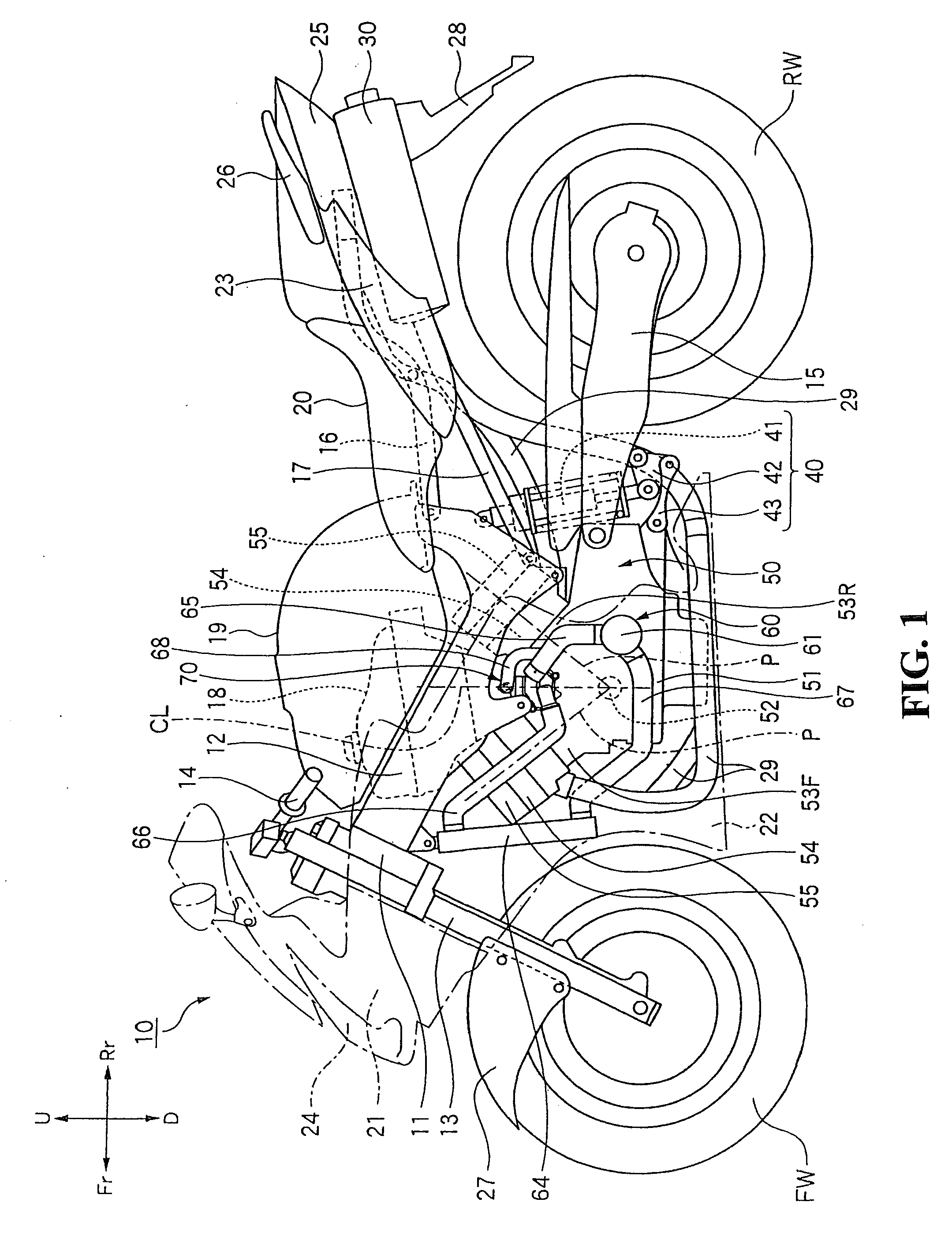
[0032]With reference to FIG. 1, a motorcycle 10 of the present embodiment includes a pair of left and right main frames 12 extending rearward and downward from a head pipe 11; a front fork 13 turnably supported by the head pipe 11; a front wheel FW rotatably supported by the lower end of the front fork 13; and steering handlebars 14 mounted to the upper end of the front fork 13. The motorcycle 10 further includes a V-type engine 50 mounte...


PUM


Abstract

A cooling water passage structure includes an engine having cylinder axes arranged in a V-shape centering on a crankshaft; water jackets formed in front and rear cylinder blocks and cylinder heads of the engine; a thermostat case having a portion formed integrally with the front and rear cylinder blocks in the V-bank of the front and rear cylinder blocks; a cooling water inlet side connecting portion 81 connecting a cooling water supply side line with a cooling water passage including the water jackets; and a cooling water outlet side connecting portion connecting a cooling water discharge side line with a cooling water passage including the water jackets. The thermostat case, the cooling water inlet side connecting portion, and the cooling water outlet side connecting portion are disposed at one end side of the engine in the direction of the crankshaft 52.

Description

TECHNICAL FIELD[0001]The present invention relates generally to a cooling water passage structure for an engine, and particularly for an engine mounted on a motorcycle.BACKGROUND OF THE INVENTION[0002]In related art, there is known a cooling water passage structure for an engine as below. This structure includes cylinders arranged in a V-shape and a cylinder block having a water jacket surrounding the cylinders. A thermostat chamber is concavely provided in a valley portion in the upper surface of the cylinder block. An impeller chamber of a water pump is concavely provided at an end face of the cylinder block. A suction water passage connecting a bottom of the thermostat chamber with the impeller chamber, a cooling water passage connecting a water pump outlet with the water jacket, and a bypass hole communicating from the thermostat chamber to the outside are provided inside the wall body of the cylinder block. A warm water tube communicating from the water jacket to a radiator and...

Claims


Application Information

Patent Timeline
Patent Type & Authority Applications(United States)
IPC IPC(8): F02F1/36
CPCF01P3/20F01P2050/16F02F7/0068F02F7/0012F02B77/089
Inventor KISAICHI, TORUNOMURA, TOMOKAZU
Owner HONDA MOTOR CO LTD
Why Eureka
Try Eureka