Integrated unit for refrigerant cycle device and manufacturing method of the same

a technology of refrigerant cycle device and integrated unit, which is applied in the operation mode of machines, light and heating apparatus, transportation and packaging, etc., can solve the problems of difficult mounting of integrated units in limited space of vehicles, reduce the size of evaporators including ejectors, and improve the mounting performance of refrigerant cycle devices. , to prevent the accuracy of the nozzle part, the effect of reducing the size of the evaporator

Inactive Publication Date: 2007-07-26
DENSO CORP
View PDF18 Cites 23 Cited by
  • Summary
  • Abstract
  • Description
  • Claims
  • Application Information

AI Technical Summary

Benefits of technology

[0011]According to another aspect of the present invention, a refrigerant cycle device includes: a compressor for compressing refrigerant; a radiator for cooling the refrigerant from the compressor; an ejector that has a nozzle part for decompressing the refrigerant from the radiator, and a refrigerant suction port from which refrigerant is drawn by a high-speed refrigerant flow jetted from the nozzle part; and an evaporator located to evaporate the refrigerant to be drawn into the refrigerant suction port or the refrigerant discharged from an outlet of the ejector. In this case, the evaporator includes a plurality of tubes defining refrigerant passages through which refrigerant flows, and a tank that is disposed at one end side of the tubes for distributing refrigerant into the tubes and for collecting the refrigerant from the tubes. The tank is provided with a hole portion for inserting the ejector at an end portion in a tank longitudinal direction, and the ejector is inserted into an inner space of the tank from the hole portion. Accordingly, the size of the evaporator including the ejector can be reduced thereby improving the mounting performance of the refrigerant cycle device.
[0012]According to a further aspect of the present invention, a manufacturing method of an integrated unit for a refrigerant cycle device includes a step of assembling evaporator members to form a heat exchanger structure that includes a plurality of tubes defining refrigerant passages through which refrigerant flows, and a tank that is disposed at one end side of the tubes and extends in a tank longitudinal direction; a step of integrally brazing the heat exchanger structure; and a step of inserting an ejector into the tank from a side of an end portion of the tank in a tank longitudinal direction, after the brazing. Because the ejector is inserted into the tube after the heat exchanger structure is brazed at a high temperature, it can prevent an accuracy of the nozzle part of the ejector from being deteriorated due to a high-temperature condition during the brazing.

Problems solved by technology

In this case, a mounting space for mounting the ejector is required outside the first and second evaporators, thereby the integrated unit may be difficult to be mounted in a limited space of the vehicle.

Method used


Image

  • Integrated unit for refrigerant cycle device and manufacturing method of the same
  • Integrated unit for refrigerant cycle device and manufacturing method of the same
  • Integrated unit for refrigerant cycle device and manufacturing method of the same

Examples


first embodiment

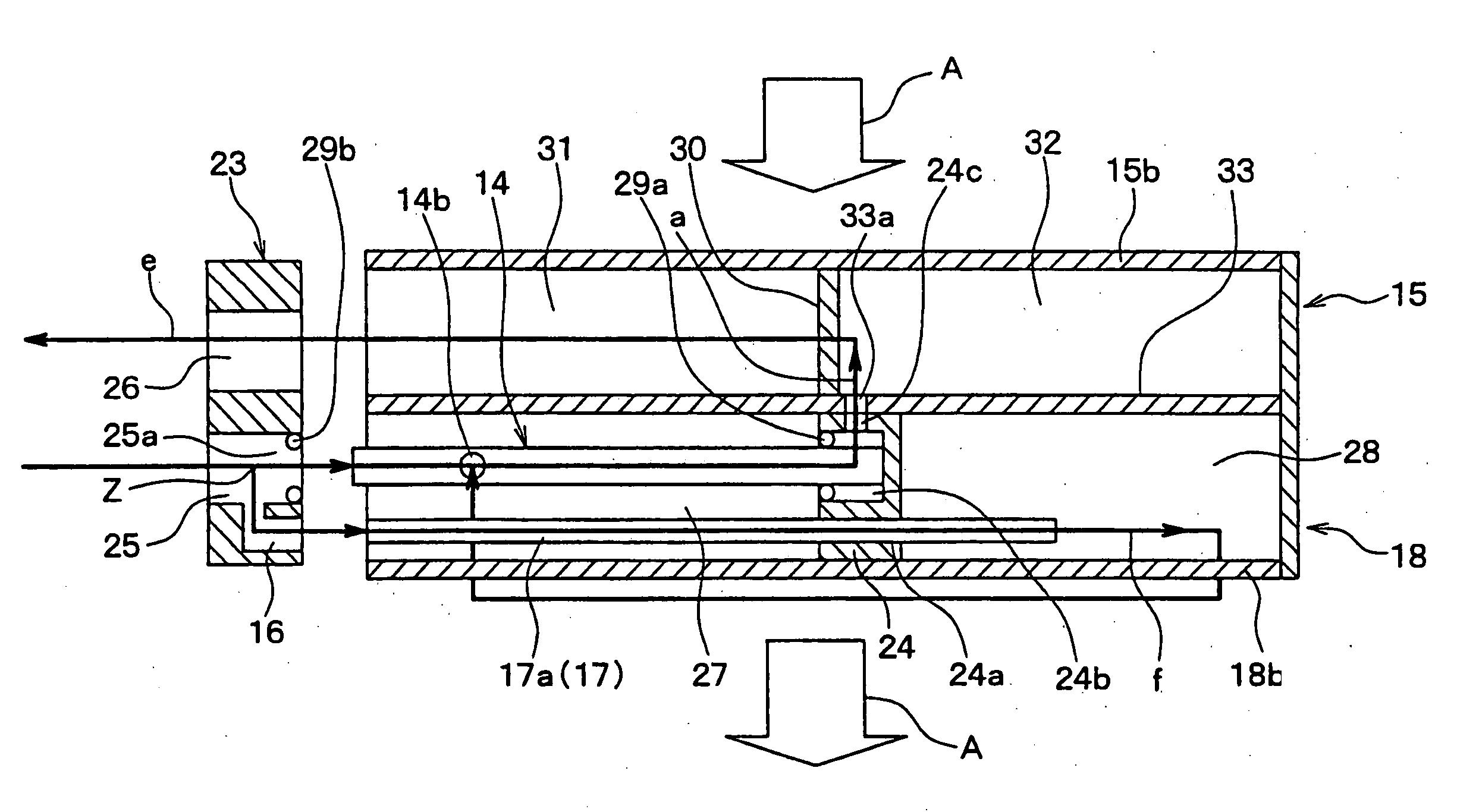
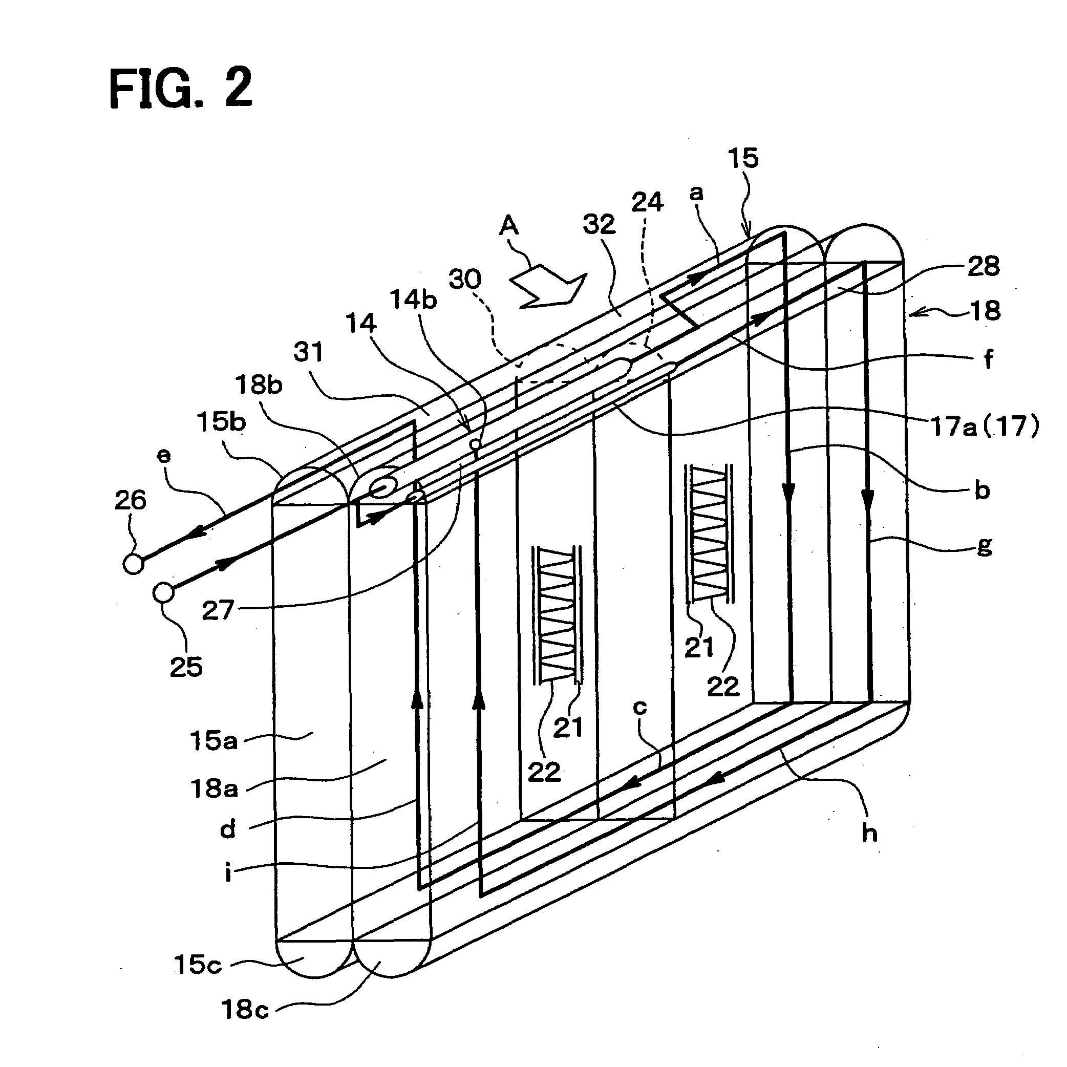
[0047]A first embodiment of the present invention will be described below with reference to FIGS. 1 to 5. In the embodiment, a heat exchanger of the present invention will be typically used for a refrigeration cycle of an ejector refrigerant cycle device. A unit for the refrigeration cycle is a heat exchanger unit, such as an ejector-equipped evaporator unit, for example.

[0048]This unit is connected to other components of the refrigeration cycle, including a condenser, a compressor, and the like, via piping to constitute a refrigerant cycle device including an ejector. The integrated unit of the embodiment is used for an indoor equipment (e.g., evaporator) for cooling air. The unit may be used as an outdoor equipment in other embodiments.

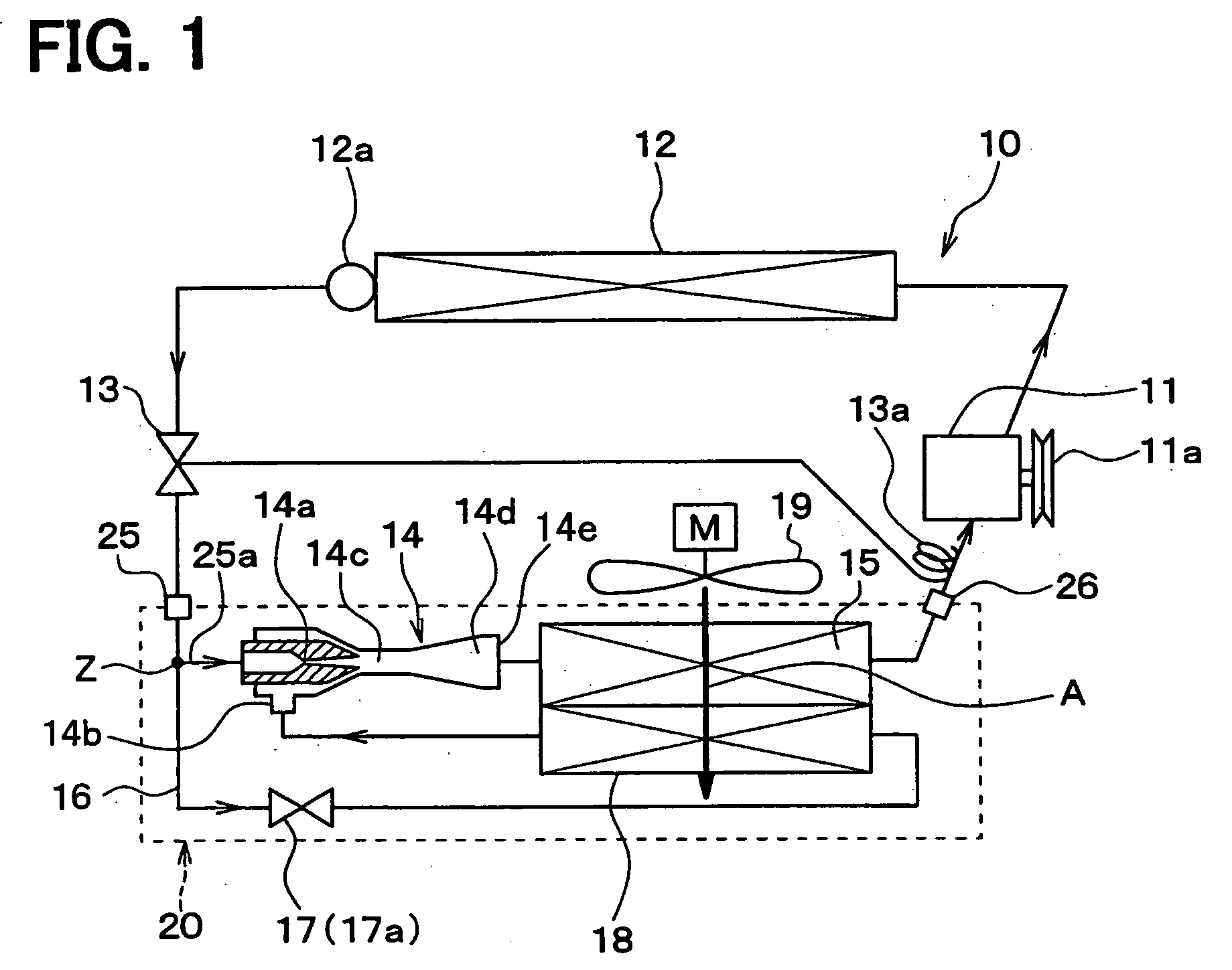
[0049]In an ejector refrigerant cycle device 10 shown in FIG. 1, a compressor 11 for drawing and compressing refrigerant is driven by an engine for vehicle traveling (not shown) via an electromagnetic clutch 11a, a belt, or the like.

[0050]As the com...

second embodiment

[0127]In the above-described first embodiment, the capillary tube 17a is disposed between the branch passage 16 of the first connection block 23 of the integrated unit 20 and the refrigerant inlet side of the second evaporator 18, so that the refrigerant from the refrigerant inlet of the second evaporator 18 is decompressed by the capillary tube 17a. However, in the second embodiment, the capillary tube 17a is not employed as the decompression means of the second evaporator 18 as shown in FIGS. 6 to 8, and instead, a fixed throttle hole 17b, such as an orifice, for restricting a path area to a predetermined level is provided on the branch passage 16 of the first connection block 23. Together with this, in the second embodiment, a connection pipe 160 whose passage diameter is larger than that of the capillary tube 17a is disposed at the position of the capillary tube 17a of the first embodiment.

[0128]An integrated unit 2 of the second embodiment has the same refrigerant passages as t...

third embodiment

[0129]Although in the above-described first embodiment, the ejector 14 and the capillary tube 17a are located in a common tank, that is, in the upper tank 18b of the second evaporator 18, in a third embodiment, as shown in FIGS. 9 to 11, only the capillary tube 17a is disposed in the upper tank 18b of the second evaporator 18, while the ejector 14 is disposed in another dedicated tank space 34.

[0130]In the third embodiment, together with removing the ejector 14 from the inside of the upper tank 18b of the second evaporator 18, the second connection block 24 employed in the first embodiment is withdrawn. Instead, a partition plate 35 is disposed approximately in the center part of the upper tank 18b in the tank longitudinal direction, and is adapted to partition the inside space of the upper tank 18b into a left space 27 and a right space 28. The tip end of the capillary tube 17a is adapted to penetrate the partition plate 35 so as to communicate with the right space 28 of the upper ...


PUM


Abstract

An integrated unit for a refrigerant cycle device includes an ejector having a nozzle part for decompressing refrigerant, and an evaporator located to evaporate the refrigerant to be drawn into a refrigerant suction port of the ejector or the refrigerant discharged from an outlet of the ejector. The evaporator includes a plurality of tubes defining refrigerant passages through which refrigerant flows, a tank that is disposed at one end side of the tubes for distributing refrigerant into the tubes and for collecting the refrigerant from the tubes. The tank extends in a tank longitudinal direction that is parallel to an arrangement direction of the tubes, and is provided with an end portion in the tank longitudinal direction. Furthermore, the end portion has a hole portion for inserting the ejector, and the ejector is inserted into an inner space of the tank from the hole portion.

Description

CROSS REFERENCE TO RELATED APPLICATION[0001]This application is based on Japanese Patent Application No. 2006-12462 filed on Jan. 20, 2006, the contents of which are incorporated herein by reference in its entirety.FIELD OF THE INVENTION[0002]The present invention relates to an integrated unit with an ejector and an evaporator for a refrigerant cycle device, and a manufacturing method of the same.BACKGROUND OF THE INVENTION[0003]An ejector refrigerant cycle device is known which includes an ejector serving as refrigerant decompression means and refrigeration circulating means. The ejector refrigerant cycle device is useful for, for example, a vehicle air conditioner, or a vehicle refrigeration system for refrigerating and freezing loads on a vehicle, or the like. The refrigerant cycle device is also useful for a fixed refrigeration cycle system, such as an air conditioner, a refrigerator, or a freezer. This kind of ejector refrigerant cycle device is disclosed in, for example, JP-B2...

Claims


Application Information

Patent Timeline
Patent Type & Authority Applications(United States)
IPC IPC(8): F25B1/06F25B39/02
CPCB60H2001/3298F25B39/02F25B2500/18F25B2341/0011F25B2341/0012F25B41/00
Inventor ISHIZAKA, NAOHISAAUNG, THUYAOSHITANI, HIROSHITAKANO, YOSHIAKIGOCHO, MIKATAKEUCHI, HIROTSUGUOKAMOTO, YOSHIYUKI
Owner DENSO CORP
Why Eureka
Try Eureka