Blower device

a blower and cylinder technology, applied in the direction of machines/engines, stators, liquid fuel engines, etc., can solve the problems of large size and weight of the entire blower device, difficulty in mounting on the vehicle, and increase the number of components of the blower device, so as to achieve the effect of convenient attachmen

Inactive Publication Date: 2008-02-14
DENSO CORP
View PDF1 Cites 9 Cited by
  • Summary
  • Abstract
  • Description
  • Claims
  • Application Information

AI Technical Summary

Benefits of technology

[0014]According to another example of the present invention, a blower device includes at least two blowers having fan shafts arranged in parallel with each other, a single motor for driving and rotating the two blowers, and a shroud for holding the two blowers. Furthermore, the motor includes a motor portion and a motor shaft driven by and extending from the motor portion, and the fan shafts of the blowers are coupled to the motor shaft via a gear portion. The shroud has two shro

Problems solved by technology

In this case, however, the number of components of the blower device is increased, and the size and weight of the entire blower device become large.
However, in this blower device, the moto

Method used


Image

  • Blower device
  • Blower device
  • Blower device

Examples


first embodiment

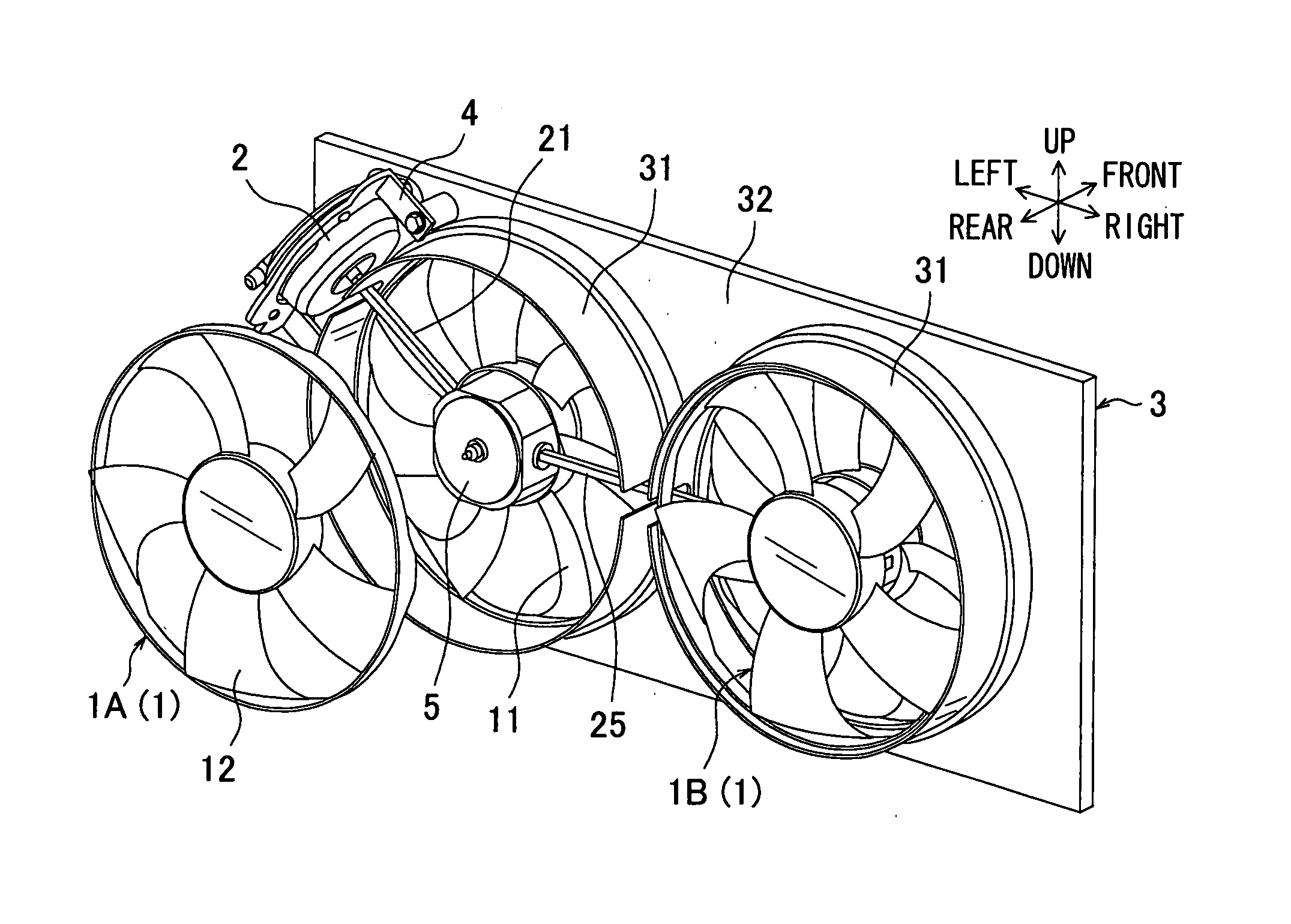
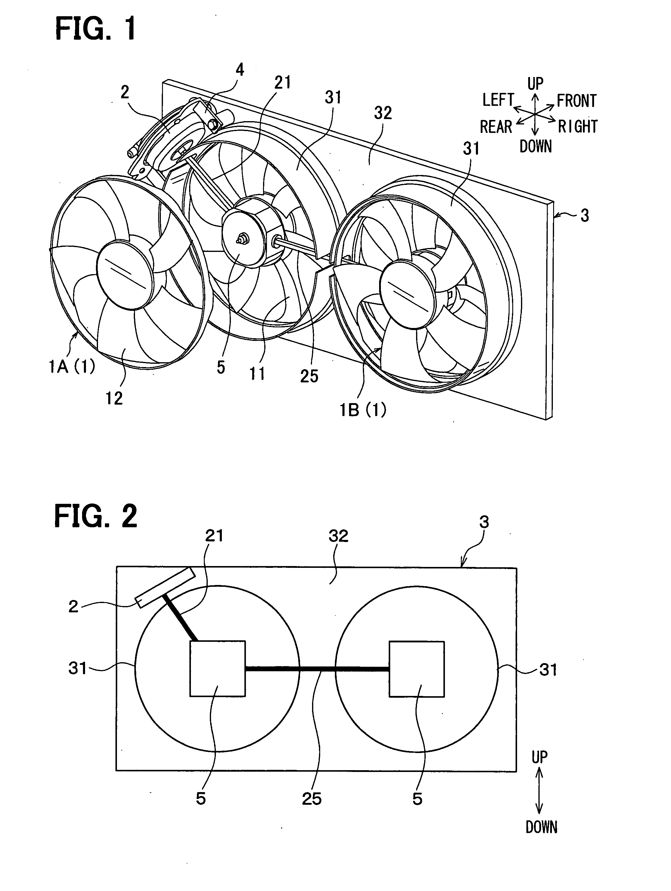
[0024]A first embodiment of the present invention will be now described with reference to FIGS. 1 to 5. In the first embodiment, a blower device of the present invention is typically used for blowing cool air to a heat exchanger such as a radiator and a condenser (refrigerant radiator) mounted on a vehicle. Here, the radiator is a heat exchanger in which engine-cooling water (hot water) from a vehicle engine is heat-exchanged with air, and the condenser is a heat exchanger in which refrigerant circulating in a refrigerant cycle is heat-exchanged with air. In the first embodiment, the radiator is located in the vehicle at a vehicle rear side from the condenser, and the blower device is located at a vehicle rear side of the radiator to blow air to the radiator and the condenser.

[0025]FIG. 1 is a disassembled perspective view showing a blower device for a vehicle, when being viewed from a vehicle rear side. The blower device includes a fan shroud 3, and blowers 1 (1A, 1B). In this embo...

second embodiment

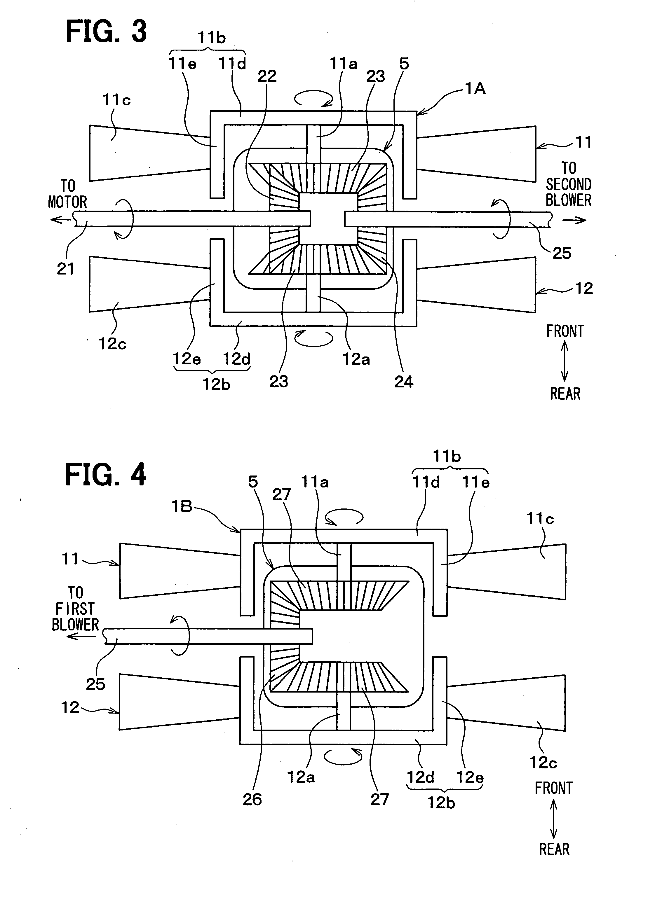
[0047]A second embodiment will be now described with reference to FIGS. 6 to 8. In the second embodiment, the parts having the same functions as those of the first embodiment are indicated by the same reference numbers as those of the first embodiment, and the detail explanation thereof is omitted. FIG. 6 shows a blower device of the second embodiment, in which the axial fans 11, 12 are omitted.

[0048]As shown in FIG. 6, in the second embodiment, the motor 2 is attached to the shroud plate portion 32 between the two shroud ring portions 31 while being offset from a center connection line connecting the centers of the shroud ring portions 31. In the example of FIG. 6, the motor 2 is located at an upper side from the center connection line connecting the centers of the adjacent two shroud ring portions 31. Furthermore, a motor shaft 21 connected to the motor 2 extends in a direction approximately perpendicular to the center connection line, that is, the arrangement direction of both th...


PUM


Abstract

A blower device for a vehicle includes at least two blowers having fan shafts arranged in parallel with each other, a single motor for driving and rotating the blowers, and a shroud for holding the two blowers. The motor includes a motor portion and a motor shaft driven by and extending from the motor portion. The shroud has shroud ring portions each of which has a circular shape to cover an outer peripheral portion of the blower, and a shroud plate portion extending from the shroud ring portions to an outside. Furthermore, the fan shafts of the blowers are coupled to the motor shaft via a gear portion, and the motor portion is attached to the shroud plate portion to be offset from a center connection line connecting the centers of the shroud ring portions.

Description

CROSS REFERENCE TO RELATED APPLICATION[0001]This application is based on Japanese Patent Application No. 2006-216494 filed on Aug. 9, 2006, the contents of which are incorporated herein by reference in its entirety.BACKGROUND OF THE INVENTION[0002]1. Field of the Invention[0003]The present invention relates to a blower device having plural blowers. For example, the blower device can be suitably used for a vehicle, for blowing air to a heat exchanger.[0004]2. Description of the Related Art[0005]In a conventional vehicle blower device for blowing air to a heat exchanger having a long length in a vehicle width direction, two axial fans are arranged on a downstream air side of a core portion of the heat exchanger, and the two axial fans are rotated respectively by two motors. That is, plural motors having the same number as plural axial fans are connected to rotation shafts of the plural axial fans, respectively. In this case, however, the number of components of the blower device is in...

Claims


Application Information

Patent Timeline
IPC IPC(8): F01D1/02
CPCF04D25/02F04D25/166F04D25/06F04D19/007
Inventor IWASAKI, TAKAHIROODA, SHINICHI
Owner DENSO CORP
Why Eureka
Try Eureka