Vehicle air conditioner

a technology for air conditioners and vehicles, applied in vehicle maintenance, vehicle cleaning, transportation and packaging, etc., can solve the problems of deteriorating the mounting performance of vehicles, increasing the temperature variation, and large door operating force, so as to improve the air-conditioning feeling of passengers adjacent to the side windshield, and improve the defogging performance of the side windshield.

Inactive Publication Date: 2010-10-05
DENSO CORP
View PDF17 Cites 12 Cited by
  • Summary
  • Abstract
  • Description
  • Claims
  • Application Information

AI Technical Summary

Benefits of technology

[0012]In view of the above-described problems, it is an object of the present invention to provide an air-outlet mode selecting device of an air conditioner for a vehicle, which can reduce a door operating force and an air flow resistance, and can improve mounting performance of the air conditioner in the vehicle.
[0014]In each of the first and second rotary doors, the outer peripheral door surface is rotated around the rotation shaft in a direction perpendicular to an air flow direction. Accordingly, door operation force of the mode selecting device can be effectively reduced, and the size of the mode selecting device can be effectively reduced. Further, because each rotary door does not partition a hot air flow and a cool air flow, a temperature difference of air blown into each opening can be reduced. In addition, because both of the rotary doors are arranged to open and close the three openings, one of the three openings can be arbitrarily arranged relative to the other two of the three openings. Thus, the size of the mode selecting device constructed with the first and second doors can be effectively reduced, and mounting performance of the air conditioner using the mode selecting device can be improved.
[0016]More preferably, the heat exchanger includes a heating heat exchanger for heating air, and the heating heat exchanger is disposed in the case to form a hot air passage through which air passes the heating heat exchanger and a cold air passage through which air bypasses the heating heat exchanger. In this case, even when the foot opening is provided to be near the cold air passage than the hot air passage, because the air passage of the case is provided with a hot air bypass passage through which air in the hot air passage is branched into right and left sides of the cold air passage and is introduced into the foot opening. Therefore, a comfortable up and down temperature distribution of air to be blown into the passenger compartment can be provided.
[0017]According to another aspect of the present invention, the first rotary door is disposed to open and close the foot opening, and the second rotary door is disposed to open and close the defroster opening and the face opening. Further, the face opening is partitioned into a center face opening portion through which air is blown toward a center upper side of the passenger compartment in a width direction of the vehicle, and a side face opening portion through which air is blown toward a side upper side of the passenger compartment in the width direction. In the air conditioner, the second rotary door is disposed to maintain an open state of the side face opening portion even while closing the center face opening portion. Therefore, it is possible to always introduce air into the side face opening portion. Accordingly, air-conditioning feeling given to a passenger adjacent to a side windshield can be improved, and defogging performance of the side windshield can be improved.

Problems solved by technology

As described above, because the doors 100, 110 need to be operated against the pressure of blowing air and the self-weight, the first type of air-outlet mode selecting device presents a problem that a door operating force becomes large.
This presents a problem of increasing variations in the temperature of air to be blown into a passenger compartment.
However, the third type of air-outlet mode selecting device, for the following reasons, deteriorates the mounting performance in a vehicle.
On the other hand, the air conditioning unit is arranged in a place that is inside the instrument panel (i.e., dashboard) of the vehicle and is subjected to extreme spatial constraint.
Thus, it is difficult to perform the arrangement of three air outlet openings of the face opening, the defroster opening and the foot opening in the shape of an arc.
As a result, the rotary door is increased in size, and the mounting performance of the air conditioning unit in the vehicle is further deteriorated.

Method used


Image

  • Vehicle air conditioner
  • Vehicle air conditioner
  • Vehicle air conditioner

Examples


first embodiment

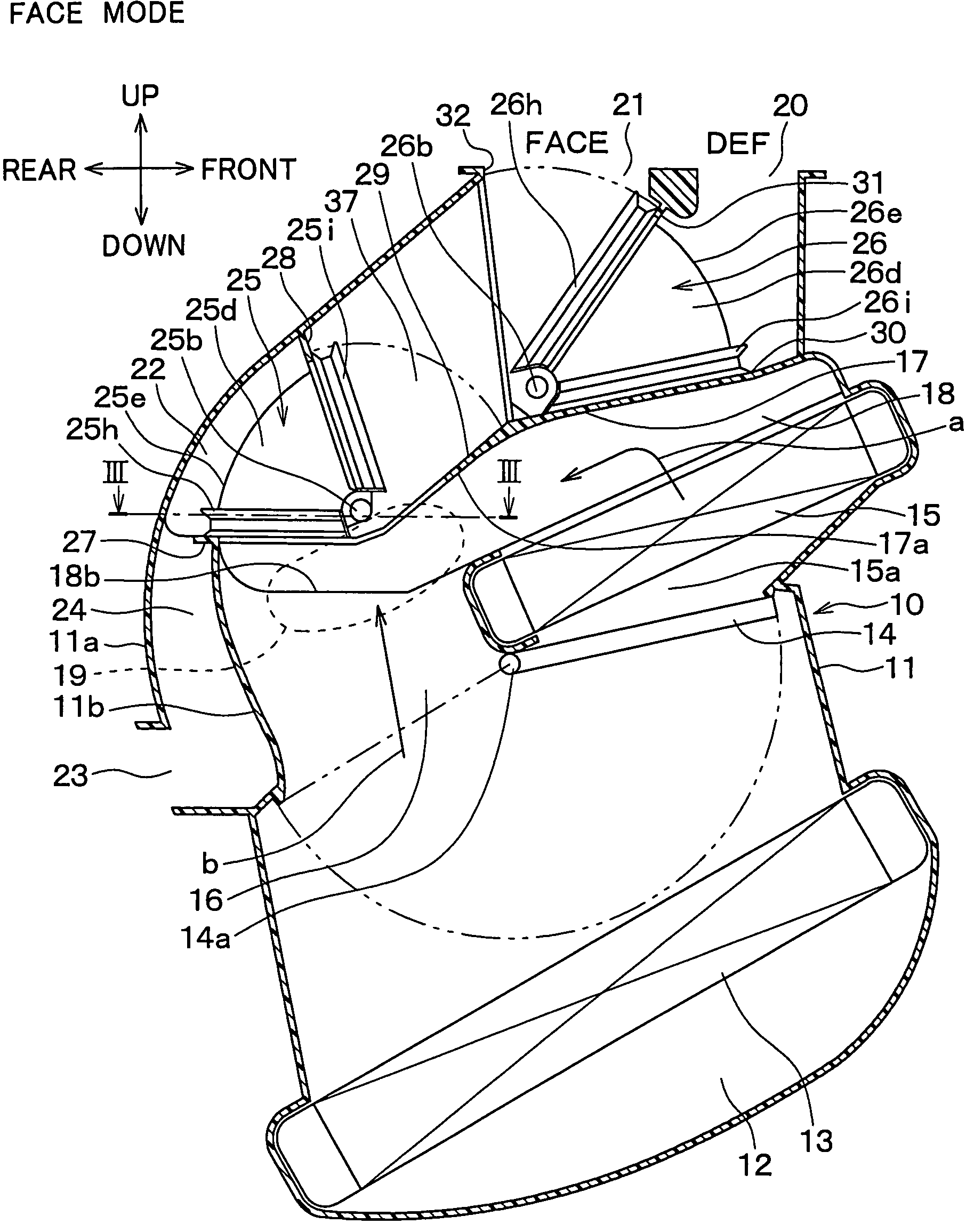
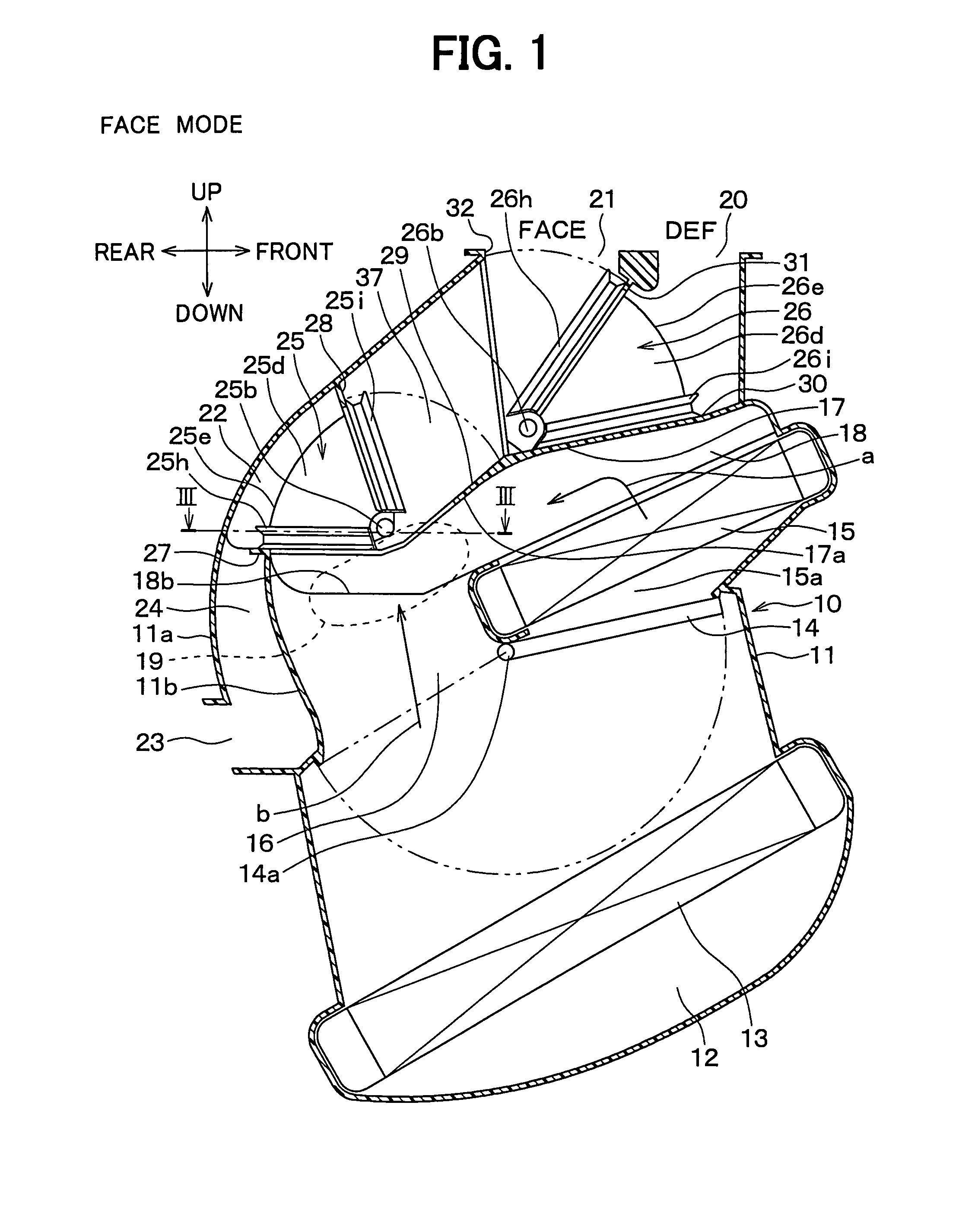
[0042]The first embodiment of the present invention will be now described with reference to FIGS. 1-7.

[0043]An air conditioning unit 10 shown in FIG. 1 is arranged nearly at the center in the width direction (right-left direction) of a vehicle inside an instrument panel (i.e., dashboard) at the front in a passenger compartment. The interior unit of an air conditioner for a vehicle is broadly divided into the above-described air conditioning unit 10 arranged nearly at the center and a blower unit (not shown) arranged in a position offset to a front passenger's seat in the width direction from the center inside the instrument panel.

[0044]The blower unit has an inside / outside air switching box for selectively introducing outside air (i.e., air outside the passenger compartment) and inside air (i.e., air inside the passenger compartment), and a centrifugal blower for blowing air introduced into this inside / outside air switching box. The air blown by this blower unit flows into a lowermo...

second embodiment

[0113]The second embodiment of the present invention will be now described with reference to FIGS. 8 and 9.

[0114]In the above-described first embodiment, a region where the first rotary door 25 is turned and a region where the second rotary door 26 is turned are set independently from each other. However, in the second embodiment, any one of the first and second rotary doors 25, 26 is arranged in a stacked manner inside the other rotary door. In this manner, the region where the first rotary door 25 is turned partially overlaps the region where the second rotary door 26 is turned.

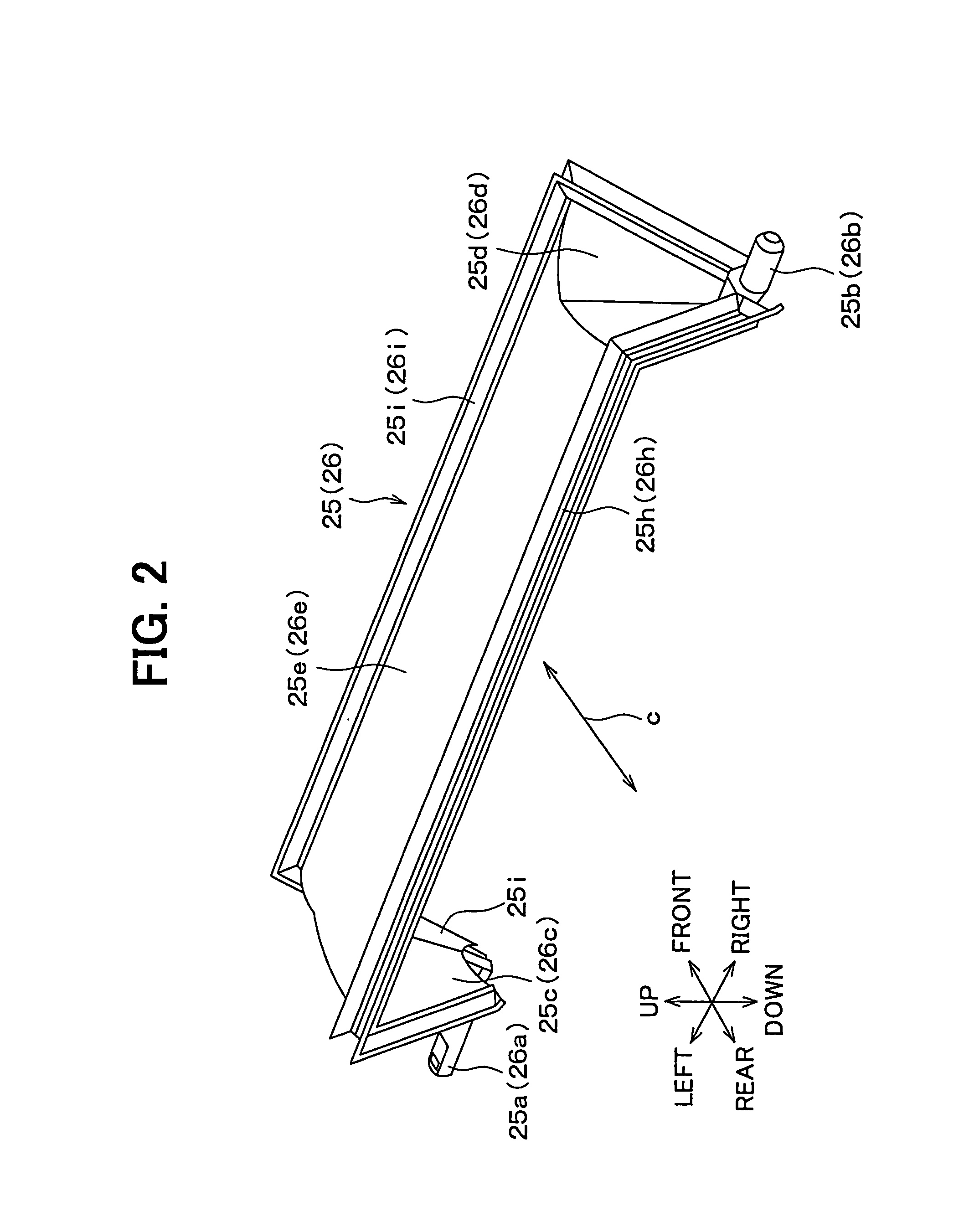
[0115]FIG. 8 and FIG. 9 show the second embodiment. FIG. 9 is a cross-sectional view taken on the line IX-IX in FIG. 8. A length L1 in an axial direction of the outer peripheral door surface 25e of the first rotary door 25 is made a specified length shorter than a length L2 in the axial direction of the outer peripheral door surface 26e of the first rotary door 26. Thus, the gate-shaped first rotary door 25...

third embodiment

[0119]The third embodiment of the present invention will be now described with reference to FIG. 10. The third embodiment is different in the arrangement of the air outlet openings 20, 21, 22 from the first and second embodiments. That is, in the third embodiment, as shown in FIG. 10, the foot openings 22 are arranged at portions near the uppermost portions of the left and right side walls of the case 11 and on the rear side of the vehicle of the defroster opening 20. In addition, the face opening 21 is arranged at a portion adjacent to the air mixing portion 19 of the wall surface on the rear side of the vehicle of the case 11.

[0120]In the air conditioner for a vehicle, an air-outlet mode is usually selected in the order of (1) face mode→(2) bi-level mode (3) foot mode→(4) foot / defroster mode→(5) defroster mode, relative to the operating direction of the actuator mechanism or the manual operation mechanism of the air-outlet mode door operation mechanism.

[0121]According to the third...


PUM


Abstract

An air-outlet mode selecting device includes first and second rotary doors. Each of the first and second rotary doors has rotary shafts separated from each other in an axial direction of the rotary shafts, an outer peripheral door surface that is provided at a position separated radial outward from the center line of the rotary shafts and is turned with the rotary shafts, and left and right side plates for connecting both ends in the axial direction of the outer peripheral surface and the rotary shafts. One of the first and second rotary doors opens and closes a specified opening among three openings and other rotary door opens and closes the remaining two openings among the three openings. Accordingly, door operation force and air flow resistance can be effectively reduced, and the size of the air-outlet mode selecting device can be effectively reduced.

Description

CROSS-REFERENCE TO RELATED APPLICATIONS[0001]This application is a divisional of U.S. patent application Ser. No. 10 / 700,721 filed on Nov. 4, 2003. This application is based on Japanese Patent Application No. 2002-321267 filed on Nov. 5, 2002, the disclosure of which is incorporated herein by reference.BACKGROUND OF THE INVENTION[0002]1. Field of the Invention[0003]The present invention relates to a vehicle air conditioner including an air-outlet mode selecting device for opening and closing air outlet openings. The air-outlet mode selecting device includes two rotary doors each of which has an outer peripheral door surface turning with a rotary shaft.[0004]2. Related Art[0005]An air-outlet mode selecting mechanism for opening and closing air outlet openings in an air conditioner for a vehicle is broadly divided into the following three types of air-outlet mode selecting devices. The first type of air-outlet mode selecting device, as shown in FIG. 22, opens and closes a defroster op...

Claims


Application Information

Patent Timeline
Patent Type & Authority Patents(United States)
IPC IPC(8): B60H1/00
CPCB60H1/00685B60H1/00842
Inventor SEKI, HIDEKIOKAWA, YOSHIHARUSHIMAUCHI, TAKAYUKI
Owner DENSO CORP
Why Eureka
Try Eureka