Systems and methods for controlling load dynamics in a pumped refrigerant cooling system

Active Publication Date: 2010-12-02
AMERICA POWER CONVERSION CORP
View PDF19 Cites 23 Cited by
  • Summary
  • Abstract
  • Description
  • Claims
  • Application Information

AI Technical Summary

Benefits of technology

[0013]Embodiments of the system include configuring the sensor package to obtain information directed to a saturation temperature. The sensor package includes a supply air temperature sensor and an evaporator pressure sensor. The cooling module further includes a pressure regulating valve disposed in the return line between the evaporator and the refrigerant distribution unit. The controller, based on the information directed to the saturation temperature, is configured to open and close the pressure regulating valve to achieve a preset saturation temperature of the cooling module. The cooling module further includes an expansion valve disposed in the supply line between refrigerant distribution unit and the evaporator. The expansion valve is being configured to meter mass flow of refrigerant into the evaporator. The controller is configured to manipulate the flow of refrigerant entering the evaporator by controlling the operation of the expansion valve. The arrangement is such that the controller manipulates the expansion valve to regulate refrigerant mass flow to the evaporator so that the refrigerant mass flow coincides with a thermal demand of the evaporator so as to assure complete evaporation of the refrigerant before exiting the evaporator. The sensor package includes a pressure sensor located immediately before the expansion valve. The sensor package includes a pressure sensor positioned to sense the pressure of evaporating refrigerant within the evaporator. The controller is configured to calculate cooling demand of the evaporator of the cooling module and established a refrigerant mass flow requirement to support a needed cooling demand of the evaporator. The controller is configured to anticipate an evaporating tempe

Problems solved by technology

Heat produced by rack-mounted equipment can have adverse effects on the performance, reliability and useful life of the equipment components.
In particular, rack-mounted equipment, housed within an enclosure, may be vulnerable to heat build-up and hot spots produced within t

Method used


Image

  • Systems and methods for controlling load dynamics in a pumped refrigerant cooling system
  • Systems and methods for controlling load dynamics in a pumped refrigerant cooling system
  • Systems and methods for controlling load dynamics in a pumped refrigerant cooling system

Examples


Embodiment Construction

[0023]This disclosure is not limited in its application to the details of construction and the arrangement of components set forth in the following description or illustrated in the drawings. The concepts described in this disclosure are capable of other embodiments and of being practiced or of being carried out in various ways. Also, the phraseology and terminology used herein is for the purpose of description and should not be regarded as limiting. The use of “including,”“comprising,” or “having,”“containing”, “involving”, and variations thereof herein, is meant to encompass the items listed thereafter and equivalents thereof as well as additional items.

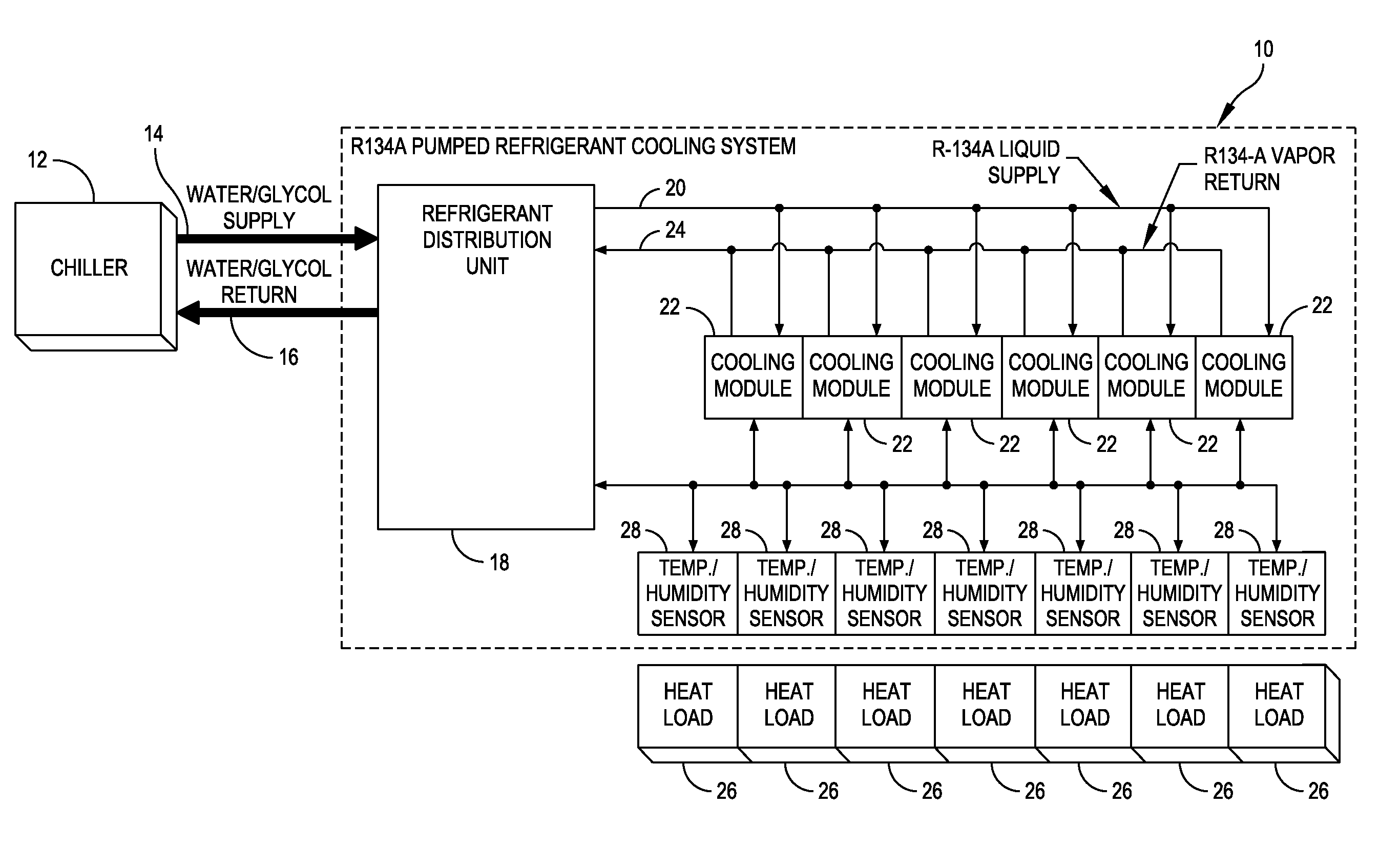
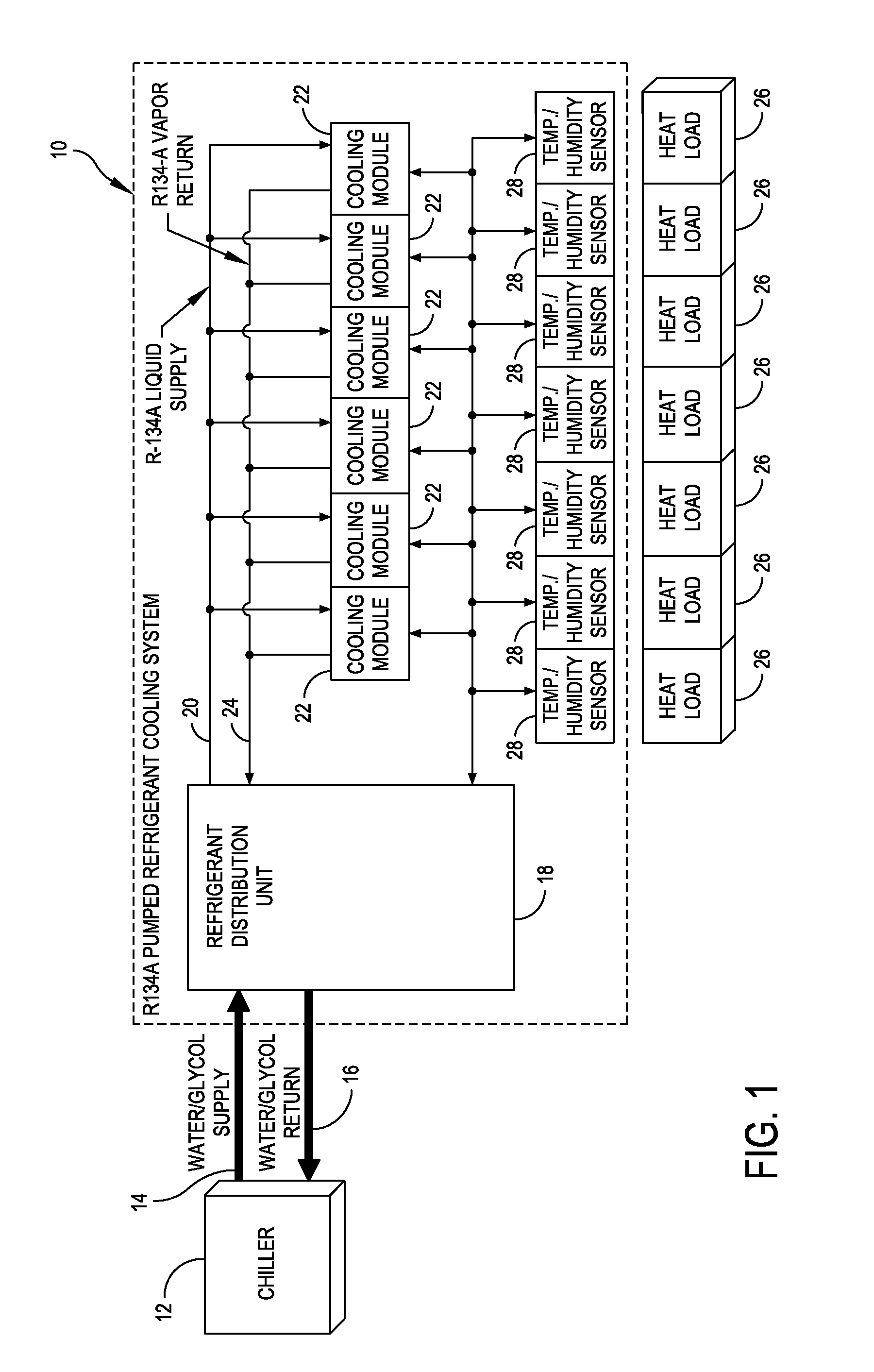
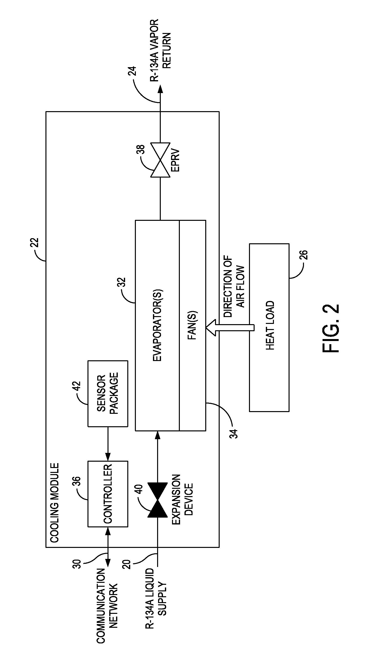
[0024]At least one embodiment of the present disclosure is directed to a cooling system that is configurable to cool electronic equipment housed within equipment enclosures or racks of a data center. As used herein, “enclosures” and “racks” are used to describe apparatus designed to support electronic equipment. Such a cooling syst...


PUM

PropertyMeasurementUnit
Temperatureaaaaaaaaaa
Pressureaaaaaaaaaa
Flow rateaaaaaaaaaa

Abstract

A pumped refrigerant cooling system for use in a row of equipment racks is configured to contain electronic equipment. The system includes a communication network and a refrigerant distribution unit in fluid communication with a chilled refrigerant supply and a heated refrigerant return. A cooling module is in fluid communication with the refrigerant distribution unit by a supply line and a return line. The cooling module is coupled to the communication network, and includes an evaporator and a fan configured to direct air over the evaporator. A sensor package is configured to monitor temperature and pressure reference points provided in the pumped refrigerant cooling system and the equipment racks. The system further includes a controller forming part of the cooling module and coupled to the communication network and the sensor package. The controller, based on information obtained from the sensor package, is configured to manipulate the flow of refrigerant through the evaporator by controlling the delivery of refrigerant to the evaporator and is configured to manipulate the flow of air over the evaporator by controlling the speed of the fan.

Description

BACKGROUND OF DISCLOSURE[0001]1. Field of Disclosure[0002]Embodiments of the disclosure relate generally to systems and methods for cooling a room, such as a data center, equipment room or wiring closet, and more specifically to systems and methods for controlling load dynamics in a pumped refrigerant cooling system that provides cooling to data centers and the like.[0003]2. Discussion of Related Art[0004]Equipment enclosures or racks for housing electronic equipment, such as data processing, networking and telecommunications equipment, have been used for many years. Such racks are often used to contain and to arrange the equipment in large equipment rooms and data centers. Over the years, a number of different standards have been developed to enable equipment manufacturers to design rack mountable equipment that can be mounted in standard racks manufactured by different manufacturers. A standard rack typically includes front mounting rails to which multiple units of electronic equi...

Claims


Application Information

Patent Timeline
IPC IPC(8): G05D23/00F28D15/00F25B39/02
CPCG05B19/042H05K7/20781H05K7/20827
Inventor BEAN, JR., JOHN H.ROESCH, JAMES RICHARDDONG, ZHIHAI GORDONDILL, STUART LEE
Owner AMERICA POWER CONVERSION CORP
Why Eureka
Try Eureka