Heat exchanger

a heat exchanger and heat exchanger technology, applied in indirect heat exchangers, lighting and heating apparatus, refrigeration components, etc., can solve the problems of requiring a considerable amount of refrigerant in flood evaporators, and achieve the effect of reducing the amount of refrigerant charge and good heat exchanger performan

Active Publication Date: 2015-01-15
DAIKIN IND LTD
View PDF6 Cites 23 Cited by
  • Summary
  • Abstract
  • Description
  • Claims
  • Application Information

AI Technical Summary

Benefits of technology

[0009]In view of the above, one object of the present invention is to provide a heat exchanger that can reduce the amount of refrigerant charge while ensuring good performance of the heat exchanger.

Problems solved by technology

Although the flooded evaporators exhibit high heat transfer performance, the flooded evaporators require a considerable amount of refrigerant because the heat transfer tubes are immersed in a pool of the liquid refrigerant.

Method used


Image

  • Heat exchanger
  • Heat exchanger
  • Heat exchanger

Examples


second embodiment

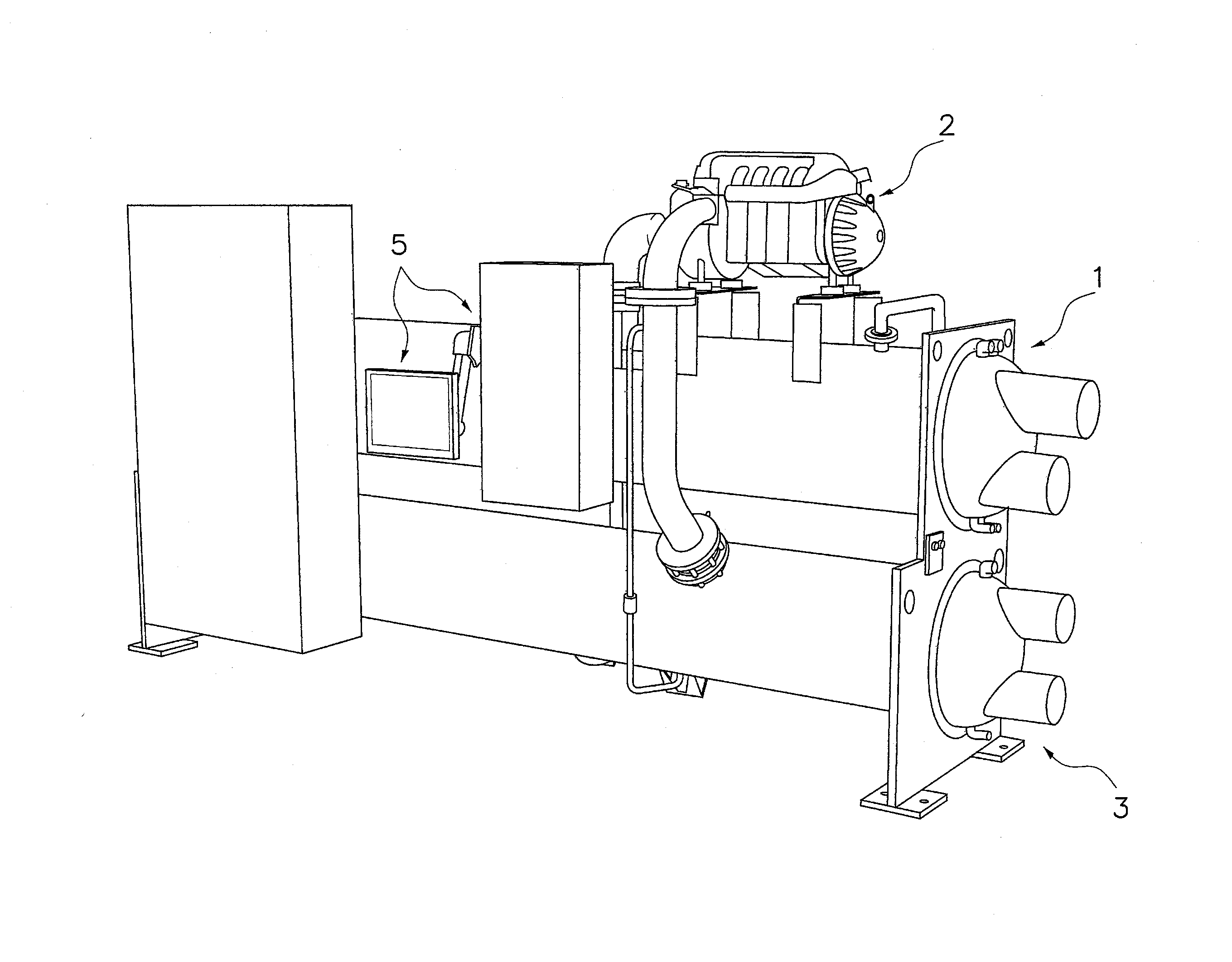
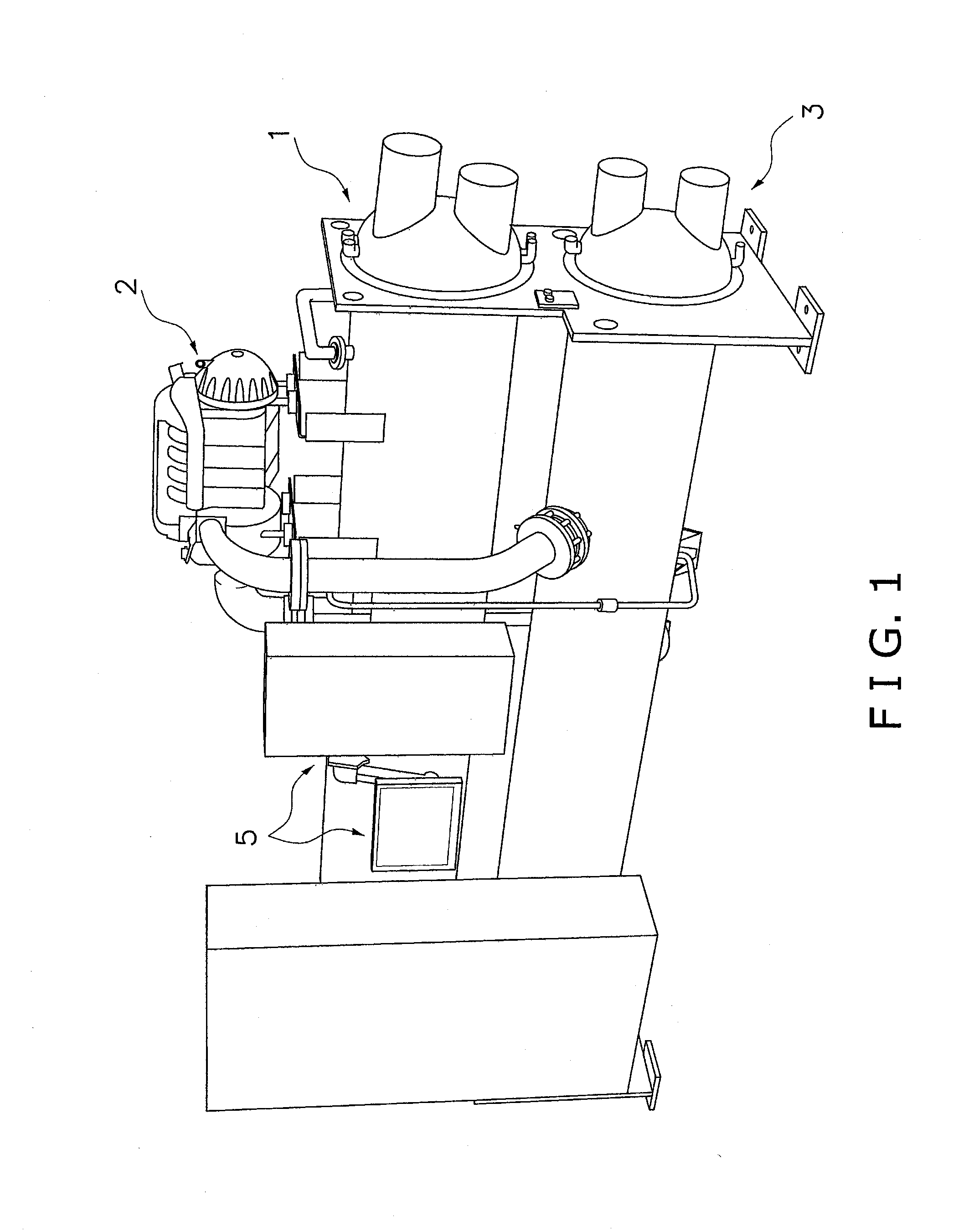
[0104]Referring now to FIG. 19, an evaporator 101 in accordance with a second embodiment will now be explained. In view of the similarity between the first and second embodiments, the parts of the second embodiment that are identical to the parts of the first embodiment will be given the same reference numerals as the parts of the first embodiment. Moreover, the descriptions of the parts of the second embodiment that are identical to the parts of the first embodiment may be omitted for the sake of brevity.

[0105]The evaporator 101 according to the second embodiment is basically the same as the evaporator 1 of the first embodiment except that the evaporator 101 of the second embodiment is provided with a refrigerant recirculation system. A trough part 140 of the second embodiment is basically the same as the trough part 40 of the first embodiment. In the first embodiment as described above, if the liquid refrigerant is distributed from the distributing part 20 over the tube bundle 30 ...

third embodiment

[0109]Referring now to FIGS. 20 to 25, an evaporator 201 in accordance with a third embodiment will now be explained. In view of the similarity between the first, second and third embodiments, the parts of the third embodiment that are identical to the parts of the first or second embodiment will be given the same reference numerals as the parts of the first or second embodiment. Moreover, the descriptions of the parts of the third embodiment that are identical to the parts of the first or second embodiment may be omitted for the sake of brevity.

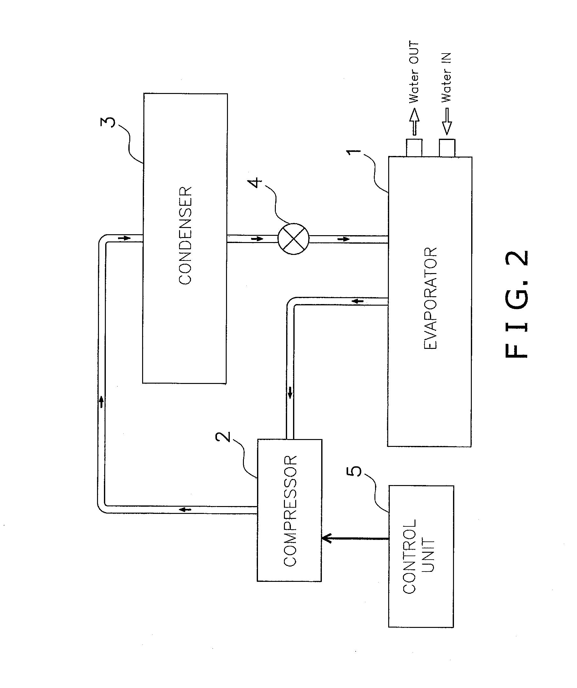
[0110]The evaporator 201 of the third embodiment is similar to the evaporator 101 of the second embodiment in that the evaporator 201 is provided with the refrigerant recirculation system, which recirculates the liquid refrigerant accumulated at the bottom portion of a shell 210 via the bottom outlet pipe 17 and the conduit 7. When the compressor 2 (FIG. 1) of the vapor compression system utilizes lubrication oil, the oil tends to migrate fr...

fourth embodiment

[0120]Referring now to FIGS. 24 and 25, an evaporator 301 in accordance with a fourth embodiment will now be explained. In view of the similarity between the first through fourth embodiments, the parts of the fourth embodiment that are identical to the parts of the first, second or third embodiment will be given the same reference numerals as the parts of the first, second or third embodiment. Moreover, the descriptions of the parts of the fourth embodiment that are identical to the parts of the first, second or third embodiment may be omitted for the sake of brevity.

[0121]The evaporator 301 of the fourth embodiment is basically the same as the evaporator 1 of the first embodiment except that an intermediate tray part 60 is provided in the falling film region F between the heat transfer tubes 31 in the supply line group and the heat transfer tubes 31 in the return line group. The intermediate tray part 60 includes a plurality of discharge openings 60a through which the liquid refrig...


PUM


Abstract

A heat exchanger includes a shell, a refrigerant distribution assembly, a heat transferring unit and a canopy member. The refrigerant distribution assembly receives a refrigerant that enters the shell and discharges the refrigerant. The refrigerant distribution assembly has at least one outermost lateral end. The heat transferring unit is disposed below the refrigerant distribution assembly so that the refrigerant discharged from the refrigerant distribution assembly is supplied to the heat transferring unit. The heat transferring unit includes a plurality heat transfer tubes. The canopy member includes at least one lateral side portion extending laterally outwardly and downwardly from a position above the refrigerant distribution assembly. The lateral side portion has a free end disposed laterally further from a vertical plane than the refrigerant distribution assembly, and lower than an upper edge of the outermost lateral end of the refrigerant distribution assembly.

Description

BACKGROUND OF THE INVENTION[0001]1. Field of the Invention[0002]This invention generally relates to a heat exchanger adapted to be used in a vapor compression system. More specifically, this invention relates to a heat exchanger including a canopy member extending from a position above a refrigerant distribution assembly.[0003]2. Background Information[0004]Vapor compression refrigeration has been the most commonly used method for air-conditioning of large buildings or the like. Conventional vapor compression refrigeration systems are typically provided with an evaporator, which is a heat exchanger that allows the refrigerant to evaporate from liquid to vapor while absorbing heat from liquid to be cooled passing through the evaporator. One type of evaporator includes a tube bundle having a plurality of horizontally extending heat transfer tubes through which the liquid to be cooled is circulated, and the tube bundle is housed inside a cylindrical shell. There are several known metho...

Claims


Application Information

Patent Timeline
Patent Type & Authority Applications(United States)
IPC IPC(8): F28F9/007
CPCF28F9/007F25B39/02F25B2339/024F28D3/02F28D3/04F28D7/163F28D2021/0071F28F9/0275F28F9/22F25B39/028F25B2339/0242F28D5/02
Inventor NUMATA, MITSUHARUKASAI, KAZUSHIGE
Owner DAIKIN IND LTD
Why Eureka
Try Eureka