Shielding assembly

a shielding assembly and shielding technology, applied in the direction of magnetic/electric field screening, electrical equipment, shielding casings, etc., can solve the problem of reducing the effectiveness of shielding assemblies

Inactive Publication Date: 2012-01-19
SHENZHEN FUTAIHONG PRECISION IND CO LTD +1
View PDF15 Cites 6 Cited by
  • Summary
  • Abstract
  • Description
  • Claims
  • Application Information

AI Technical Summary

Benefits of technology

[0004]A typical portable electronic device, such as a mobile phone, generally includes a printed circuit board with one or more electrical components and a shielding assembly mounted to the printed circuit board for shielding the electrical components. The shielding assembly generally includes a frame with a plurality of holes and a cover punched to form a number of bent portions with a number of protrusions formed on the bent portions. Each protrusion latches in one of the holes to latch the frame to the cover. However, a number of openings will be defined through the cover adjacent when the bent portions are formed reducing the effectiveness of the shielding assembly.

Problems solved by technology

However, a number of openings will be defined through the cover adjacent when the bent portions are formed reducing the effectiveness of the shielding assembly.

Method used


Image

  • Shielding assembly
  • Shielding assembly
  • Shielding assembly

Examples


Embodiment Construction

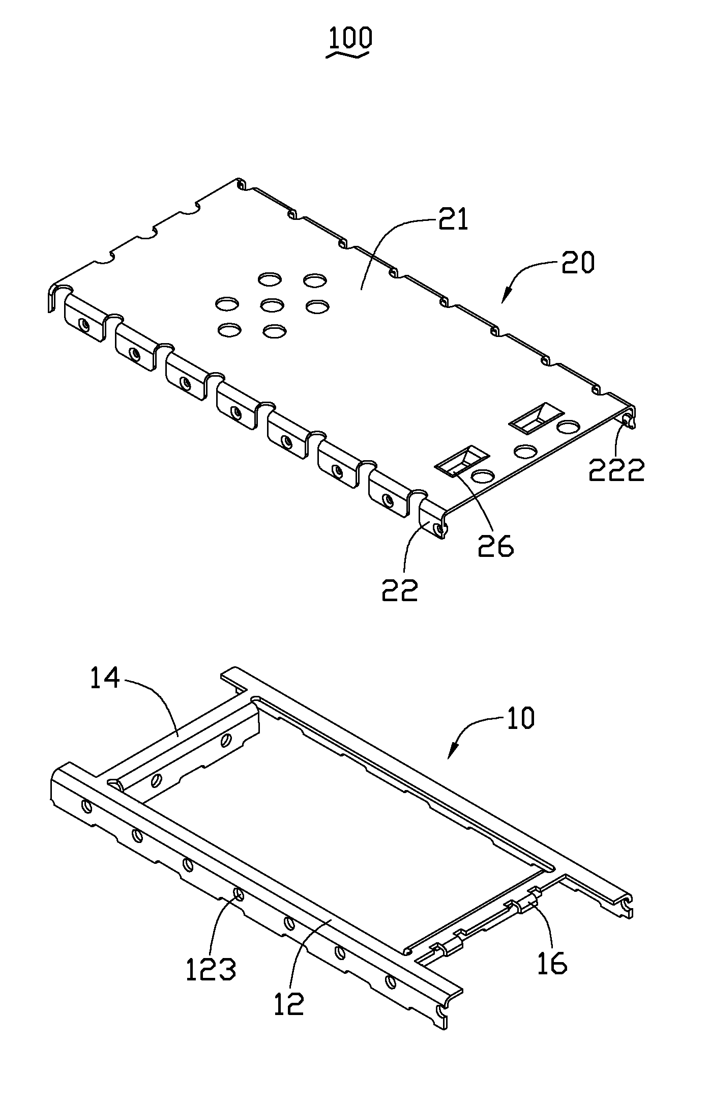
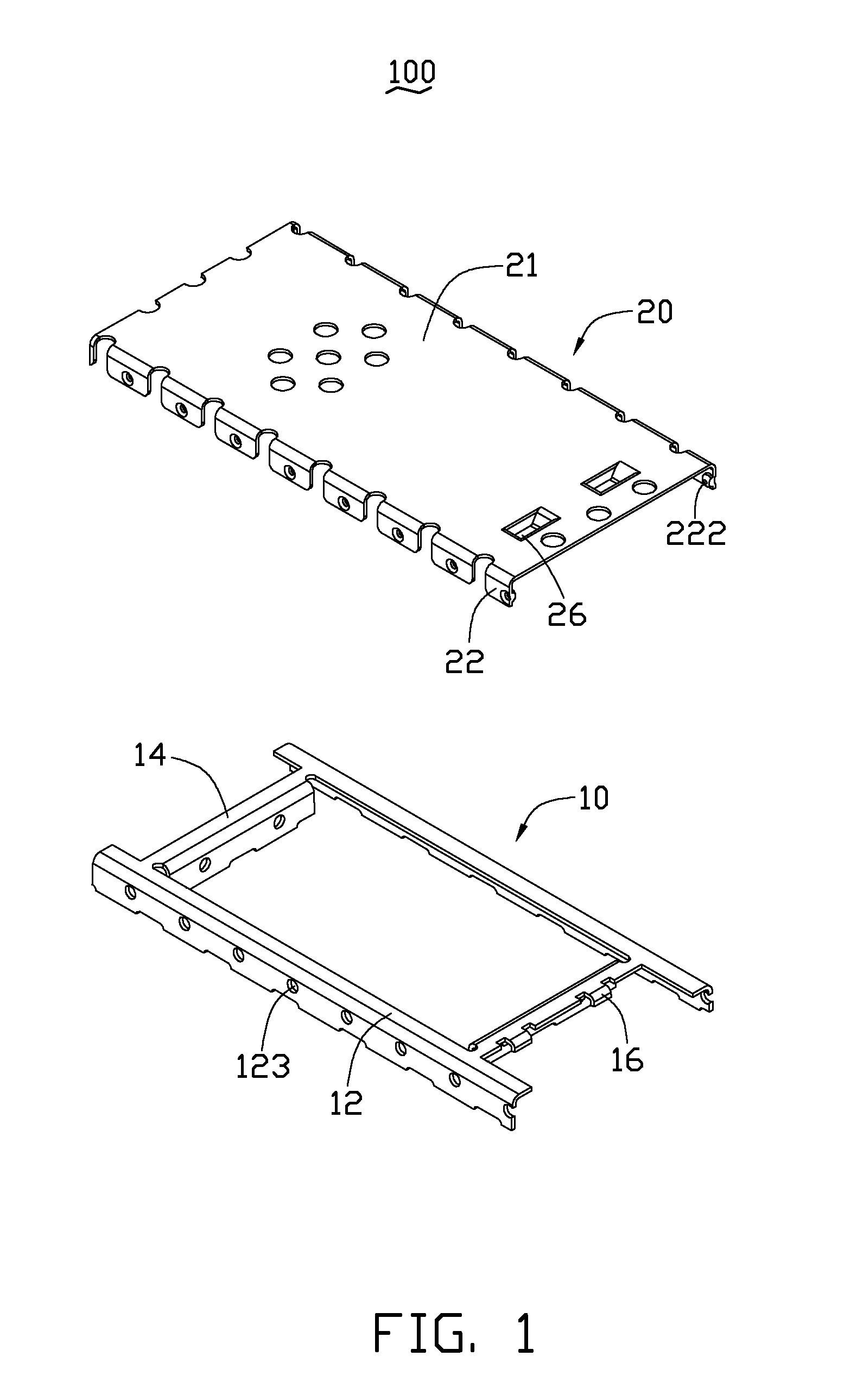
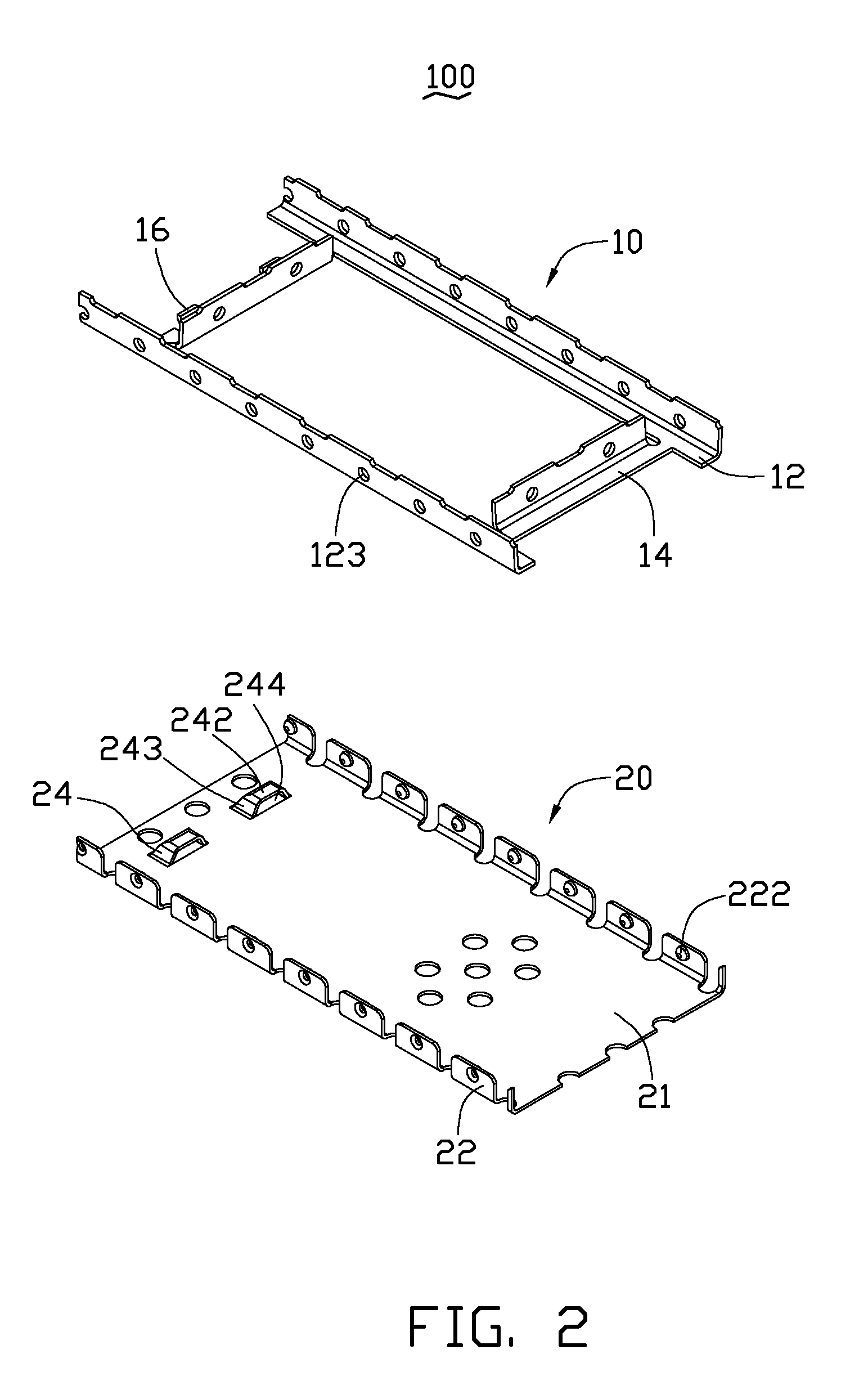
[0011]Referring to FIGS. 1-4, a shielding assembly 100 includes a frame 10 and a cover 20 latched to the frame 10. The frame 10 may be mounted to a circuit board of an electronic device (not shown), for accommodating electrical components of the electronic device. The frame 10 may be formed by punching a metallic plate and includes two opposite sidewalls 12, two opposite end walls 14 and at least one catch 16, such as two catches 16. The end walls 14 respectively connect with the sidewalls 12. Each sidewall 12 further defines a plurality of holes 123. The catches 16 are both protruding from one of the end walls 14, and are substantially L-shaped (FIG. 4).

[0012]The cover 20 includes a main body 21, a plurality of bent portions 22 protruding from two sides of the main body 21, and at least one latching portion 24, such as two latching portions 24 positioned near one end of the main body 21 corresponding to the catches 16. Each bent portion 22 has a protrusion 222 protruding from an in...


PUM


Abstract

A shielding assembly includes a frame including a catch protruding near one end thereof; and a cover including a main body. The main body is punched to form an opening and a latching portion protruding from the main body and aligned with the opening; the latching portion latches with the catch, the latching portion shields the opening to improve the shielding affect of the shielding assembly.

Description

BACKGROUND[0001]1. Technical Field[0002]This disclosure relates to shielding assemblies, particularly to a shielding assembly for portable electronic devices.[0003]2. Description of Related Art[0004]A typical portable electronic device, such as a mobile phone, generally includes a printed circuit board with one or more electrical components and a shielding assembly mounted to the printed circuit board for shielding the electrical components. The shielding assembly generally includes a frame with a plurality of holes and a cover punched to form a number of bent portions with a number of protrusions formed on the bent portions. Each protrusion latches in one of the holes to latch the frame to the cover. However, a number of openings will be defined through the cover adjacent when the bent portions are formed reducing the effectiveness of the shielding assembly.[0005]Therefore, there is a room for improved in the art.BRIEF DESCRIPTION OF THE DRAWINGS[0006]Many aspects of the embodiment...

Claims


Application Information

Patent Timeline
Patent Type & Authority Applications(United States)
IPC IPC(8): H05K9/00
CPCH05K9/0037H05K9/0007
Inventor CAO, GUANG-FEI
Owner SHENZHEN FUTAIHONG PRECISION IND CO LTD
Why Eureka
Try Eureka