Optical fiber manufacturing device and optical fiber manufacturing method

a manufacturing device and optical fiber technology, applied in the direction of glass making apparatus, manufacturing tools, instruments, etc., can solve the problems of affecting the appearance external appearance affecting the strength of the optical fiber, scratching of the inner coating layer, etc., to achieve the effect of suppressing the eccentricity of the coating layer, simple configuration, and high drawing speed

Inactive Publication Date: 2010-12-23
THE FUJIKURA CABLE WORKS LTD
View PDF6 Cites 5 Cited by
  • Summary
  • Abstract
  • Description
  • Claims
  • Application Information

AI Technical Summary

Benefits of technology

[0037]According to an exemplary embodiment, an optical fiber traveling between a coating unit and a rotating body can be made to follow a desired path-line. Thus, even if the drawing speed is high at 1500 m/min or more, the path-line of a bare optical fiber as it passes the coating unit can be prevented from greatly fluctuating with respect to the coating unit,...

Problems solved by technology

If the bare optical fiber makes contact with these components, there is a possibility that it will be damaged and its strength will deteriorate.
If the inner coating layer of the optical fiber makes contact, there is a possibility that the surface of the inner coating layer will be scratched, roughing the interface with the outer coating layer, marring an external appearance of the opt...

Method used


Image

  • Optical fiber manufacturing device and optical fiber manufacturing method
  • Optical fiber manufacturing device and optical fiber manufacturing method
  • Optical fiber manufacturing device and optical fiber manufacturing method

Examples


first exemplary embodiment

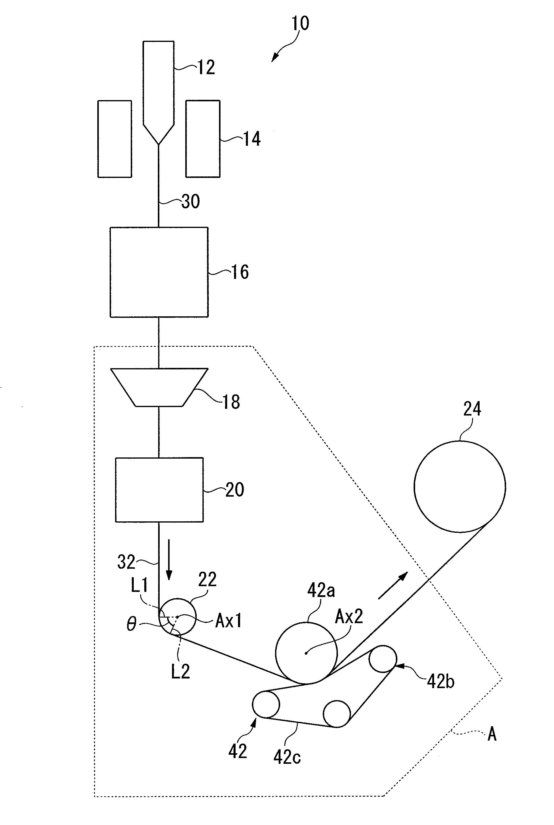
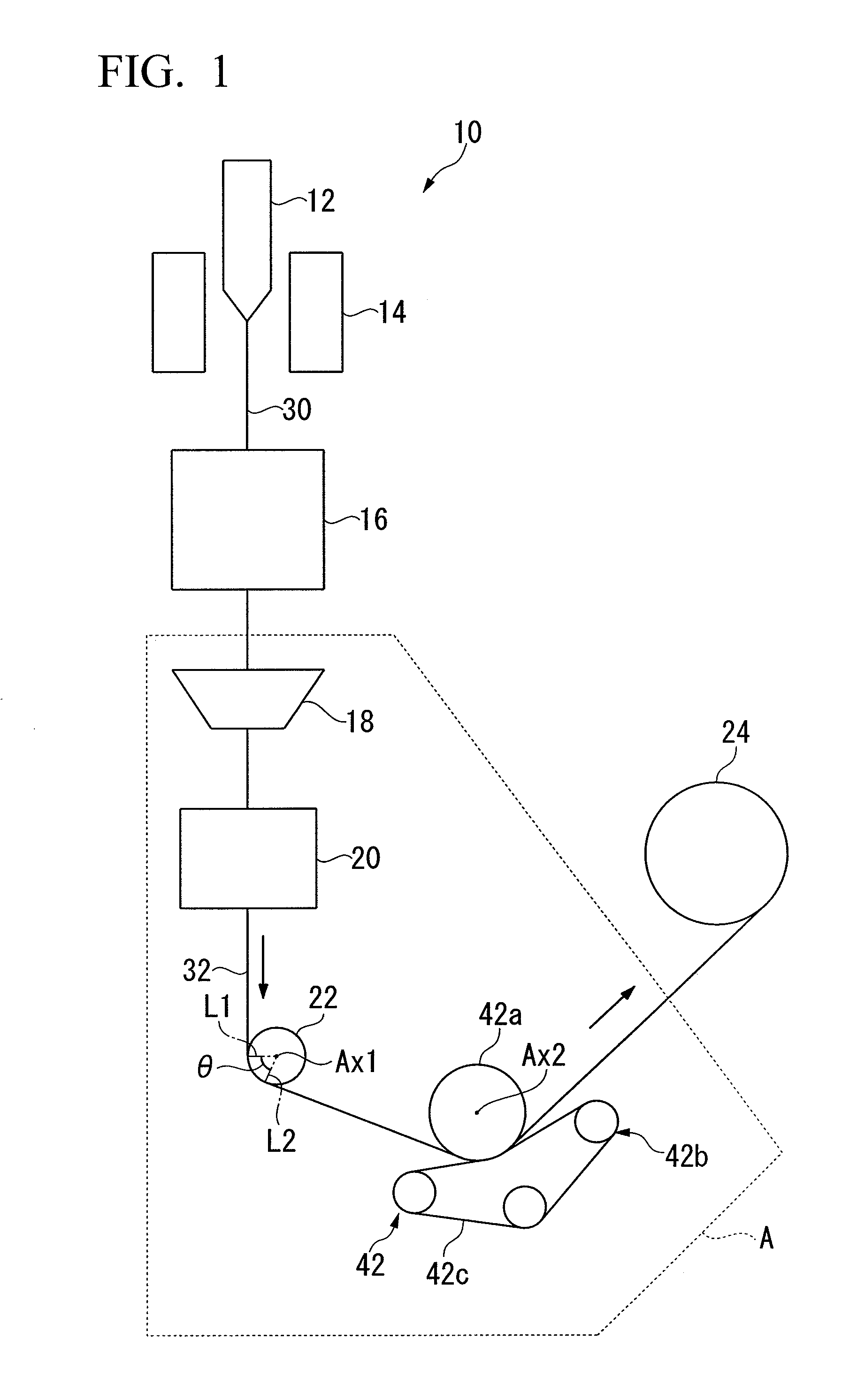
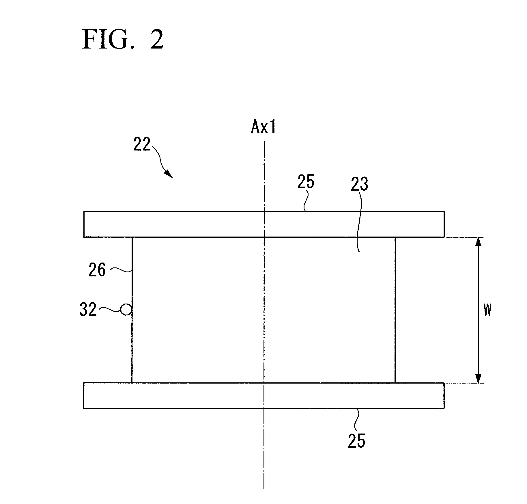
[0050]FIG. 1 is an explanatory view of an optical fiber manufacturing device 10 according to a first exemplary embodiment of the invention. The optical fiber manufacturing device 10 includes a heating furnace 14 (bare optical fiber-forming unit), a cooler 16, a coating unit 18, a resin-curing unit 20, a pulley 22 (first direction-converter), a capstan 42, and a winder 24. The heating furnace 14 is arranged at the topmost part, the cooler 16 is arranged immediately and coaxially below (downstream from) the heating furnace 14, and the coating unit 18 and the resin-curing unit 20 are provided immediately below (downstream from) the cooler 16, being arranged substantially coaxially in that sequence.

[0051]In an optical fiber drawing step using the optical fiber manufacturing device 10, an optical fiber preform 12 is heat-melted in the heating furnace 14 at a temperature of approximately 2000° C., and a bare optical fiber 30 is drawn out while ensuring that its outer diameter is constant....

second exemplary embodiment

[0071]FIG. 7 is an explanatory view of an optical fiber manufacturing device 40 according to a second exemplary embodiment of the invention. Constituent elements of the optical fiber manufacturing device 40 shown in FIG. 7 that are identical to or correspondent with those of the optical fiber manufacturing device 10 shown in FIG. 1 are designated with identical reference numerals, and are not repetitiously explained.

[0072]In the optical fiber manufacturing device 40, an optical fiber 32 extracted from the resin-curing unit 20 is made to contact with the capstan 42 without first passing a pulley. The capstan 42 first changes the traveling direction of the optical fiber 32 in a direction, shown as toward the bottom right in FIG. 7, the pulley 22, having an axis of rotation Ax1 with a fixed position, changes the traveling direction again in a direction, shown as toward the top right in FIG. 7, and the optical fiber 32 is then wound in the winder 24. A rotating body 42a of the capstan 4...

third exemplary embodiment

[0077]FIG. 8 is an explanatory view of an optical fiber manufacturing device 50 according to a third exemplary embodiment of the invention. Constituent elements of the optical fiber manufacturing device 50 shown in FIG. 8 which are identical to or correspondent with those of the optical fiber manufacturing device 10 shown in FIG. 1 are designated by identical reference numerals, and are not repetitiously explained.

[0078]In the optical fiber manufacturing device 50, a pulley 22, which first changes the traveling direction of an optical fiber 32 after it has been extracted from a resin-curing unit 20, and a rotating body 42a of a capstan 42 with which the optical fiber 32 subsequently contacts after passing the pulley 22, are arranged such that they rotate in mutually opposite directions as the optical fiber 32 passes. The structure of the pulley 22 is the same as that shown in FIG. 2. The position of the axis of rotation Ax2 of the rotating body 42a, which is the solid body with whic...


PUM

PropertyMeasurementUnit
Angleaaaaaaaaaa
Angleaaaaaaaaaa
Speedaaaaaaaaaa

Abstract

An optical fiber manufacturing device includes a bare optical fiber-forming unit that forms a bare optical fiber by pulling an optical fiber preform; a coating unit that forms an optical fiber by coating the bare optical fiber outputted from the bare optical fiber-forming unit with a coating layer; a first direction-converter, which is a solid body that comes into contact with the optical fiber outputted from the coating unit and thereby first changing its traveling direction; and a winder that winds the optical fiber obtained from the first direction-converter, in which: the first direction-converter is a rotating body having a circumferential face that contacts with the optical fiber and is formed around an axis of rotation thereof; and the contact angle, centered on the axis of rotation, between this rotating body and the optical fiber is in the range of 10° to 80°.

Description

[0001]The present Application claims priority from Japanese Patent Application No. 2008-282506, filed Oct. 31, 2008, the content of which is incorporated herein by reference.TECHNICAL FIELD[0002]Apparatuses and methods consistent with the present invention relate to an optical fiber manufacturing device and an optical fiber manufacturing method that manufacture an optical fiber by drawing an optical fiber from an optical fiber preform.BACKGROUND[0003]Generally, optical fiber drawing is performed with an optical fiber manufacturing device (not shown) by steps such as the following.[0004]Firstly, an optical fiber preform is inserted into a heating furnace, and a front end of the optical fiber preform is heat-melted at a temperature of approximately 2000° C. to form a bare optical fiber, which is removed from the heating furnace. The removed bare optical fiber is then cooled to a temperature at which it can be coated. In a coating unit of the optical fiber manufacturing device, the coo...

Claims


Application Information

Patent Timeline
IPC IPC(8): C03C25/10C03B37/02
CPCC03B37/032C03C25/12C03B2205/42Y02P40/57C03B37/01G02B6/00
Inventor OKADA, KENJI
Owner THE FUJIKURA CABLE WORKS LTD
Why Eureka
Try Eureka