Beveled edge thin cutting knife

a thin cutting knife and beveled edge technology, applied in the field of knives, can solve the problems of difficult, if not impossible, to effectively and economically produce a relatively sharp cutting edge on these knives, and it is difficult to effectively and economically form a tapered or beveled edge onto the relatively thin material of these knives, so as to reduce the effectiveness of cutting action.

Active Publication Date: 2007-11-06
KOOIMA PHILLIP
View PDF5 Cites 4 Cited by
  • Summary
  • Abstract
  • Description
  • Claims
  • Application Information

AI Technical Summary

Benefits of technology

[0012]One significant advantage of the present invention is the formation of a relatively sharp edge on a relatively thin blade material in a manner that does not produce sharp interior corners that catch and collect crop materials, thus reducing the effectiveness of the cutting action.

Problems solved by technology

However, due to the relative thinness of the material used to form the knife, it has been relatively difficult, if not impossible, to effectively and economically produce a relatively sharp cutting edge on these knives for use on agricultural crop processing machinery.
In particular, it has been established that it is relatively difficult to effectively and economically form a tapered or beveled edge onto the relatively thin material of these knives in the conventional manner for shaping knives formed of material thicker than 7 gauge, which is to using a milling machine.
Further, when such milling is attempted, a relatively sharp and confined corner is necessarily created between adjacent teeth on the knife.
This collection of crop material on the knife tends to reduce the effectiveness of the cutting capability of the adjacent teeth as the crop material is blocked from coming into contact with the blunt cutting edge.

Method used


Image

  • Beveled edge thin cutting knife
  • Beveled edge thin cutting knife
  • Beveled edge thin cutting knife

Examples


Embodiment Construction

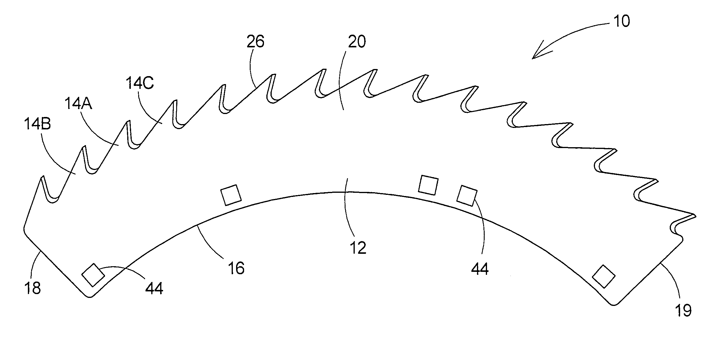
[0021]With reference now to the drawings, and in particular to FIGS. 3 through 6 thereof, a new beveled edge thin cutting knife embodying the principles and concepts of the present invention and generally designated by the reference numeral 10 will be described.

[0022]As best illustrated in FIGS. 3 through 6, the beveled edge thin cutting knife 10 generally comprises a knife for mounting on a harvesting apparatus that is employed to cut and process a crop material, such as, for example, corn materials and the like.

[0023]The knife 10 includes a base portion 12 and a plurality of teeth 14a, 14b, 14c that each extend from the base portion. The base portion 12 has an interior edge 16 and a pair of end edges 18, 19. The base portion 12 has an exterior region 20 that is located opposite of the interior edge 16. The base portion 12 has opposite major faces 22, 24, which are oriented substantially parallel to each other. One of the major faces is an upper major face 22 for orienting in an up...


PUM

PropertyMeasurementUnit
bevel angleaaaaaaaaaa

Abstract

A knife is disclosed for cutting crop materials, and includes a base portion having an interior edge and a pair of end edges. The base portion has an exterior region opposite the interior edge and has opposite major faces. The knife further includes a plurality of teeth extending from the base portion, with each tooth being defined by a perimeter edge. The perimeter edge of the tooth includes a leading edge portion and a transition edge portion extending between the leading edge portion of the tooth and an adjacent tooth. The leading edge portion is formed by a leading edge surface lying substantially in a plane that is oriented at a first bevel angle with respect to one of the major faces. The transition edge portion is formed by a transition edge surface that is oriented with respect to one of the major faces at a second bevel angle.

Description

BACKGROUND OF THE INVENTION[0001]1. Field of the Invention[0002]The present invention relates to knifes for cutting and chopping crop materials, and more particularly pertains to a new beveled edge thin cutting knife for increasing the cutting effectiveness of agricultural crop harvesting and processing equipment.[0003]2. Description of the Prior Art[0004]Crop harvesting machines, such as combines and forage harvesters, often employ “heads” mounted on the front of the machinery to gather and cut the plant as it stands in the field at harvest time. Some types of heads, such as a head designed for use in the harvest of corn, includes a number of snouts, or finger-like structures that extend forwardly of the machine, to guide and gather the plants as they stand in rows in the field. The corn head also includes a number of knifes or blades that cut the upper portion of the plant off from the lower portion of the plant as the plant moves between the snouts, so that the upper portion of t...

Claims


Application Information

Patent Timeline
Patent Type & Authority Patents(United States)
IPC IPC(8): B27B33/02
CPCA01D34/73Y10T83/9319Y10T83/9348
Inventor KOOIMA, PHILLIP
Owner KOOIMA PHILLIP
Why Eureka
Try Eureka