Wrench with ergonomic twisted handle

a twisting handle and wrench technology, applied in the field of wrenches, can solve the problems of unfit ergonomic design and inconvenient use of conventional wrenches, and achieve the effect of improving user comfort and facilitation of operation

Inactive Publication Date: 2012-01-26
CHANG CHIH MIN
View PDF10 Cites 7 Cited by
  • Summary
  • Abstract
  • Description
  • Claims
  • Application Information

AI Technical Summary

Benefits of technology

[0006]It is one objective of the present invention to provide a wrench, which has an ergonomic twisted handle design so as to improve user comfort and facilitation in operation.

Problems solved by technology

In other word, the conventional wrench 10 is unfit for ergonomic design and inconvenient to use.

Method used


Image

  • Wrench with ergonomic twisted handle
  • Wrench with ergonomic twisted handle
  • Wrench with ergonomic twisted handle

Examples


Embodiment Construction

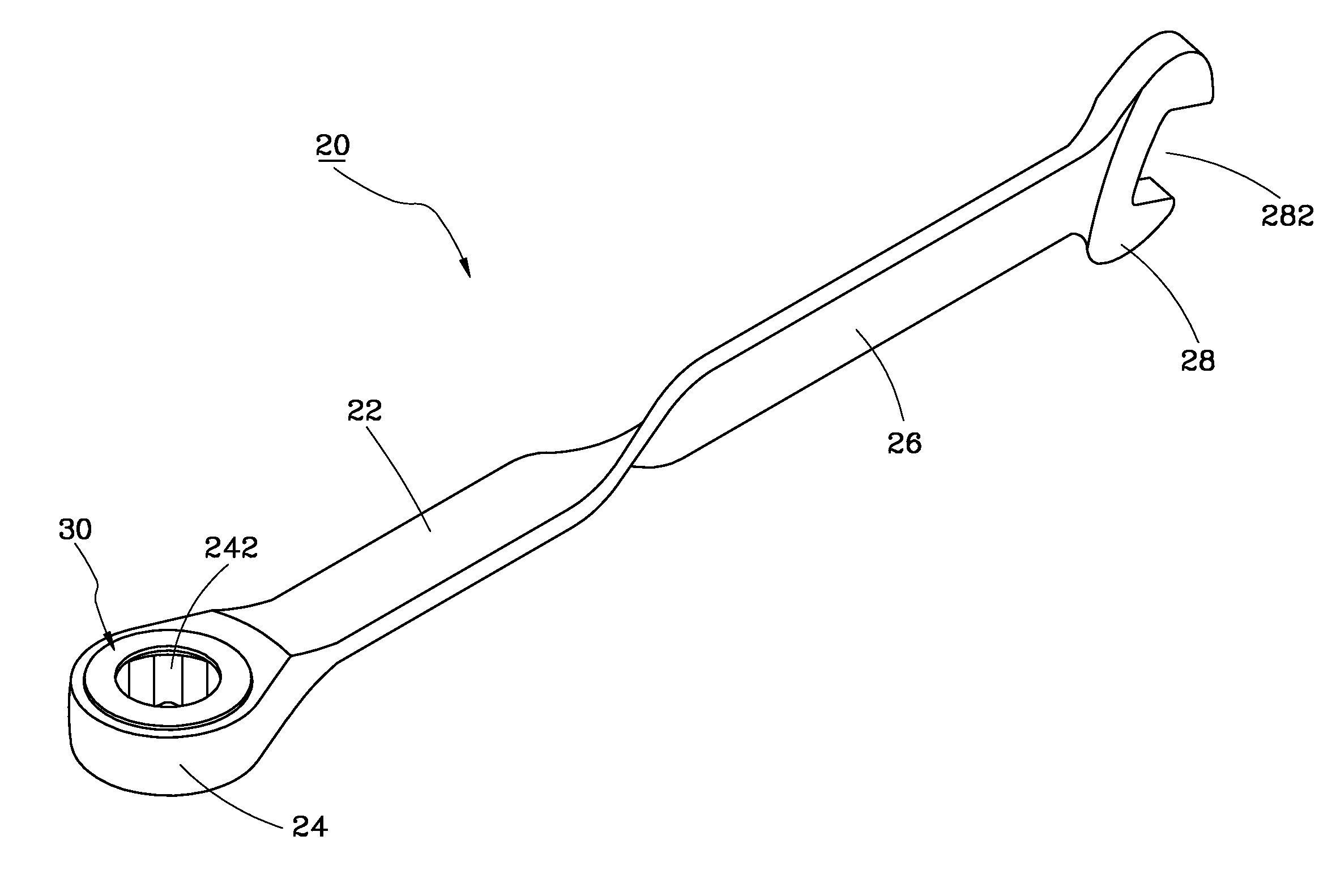
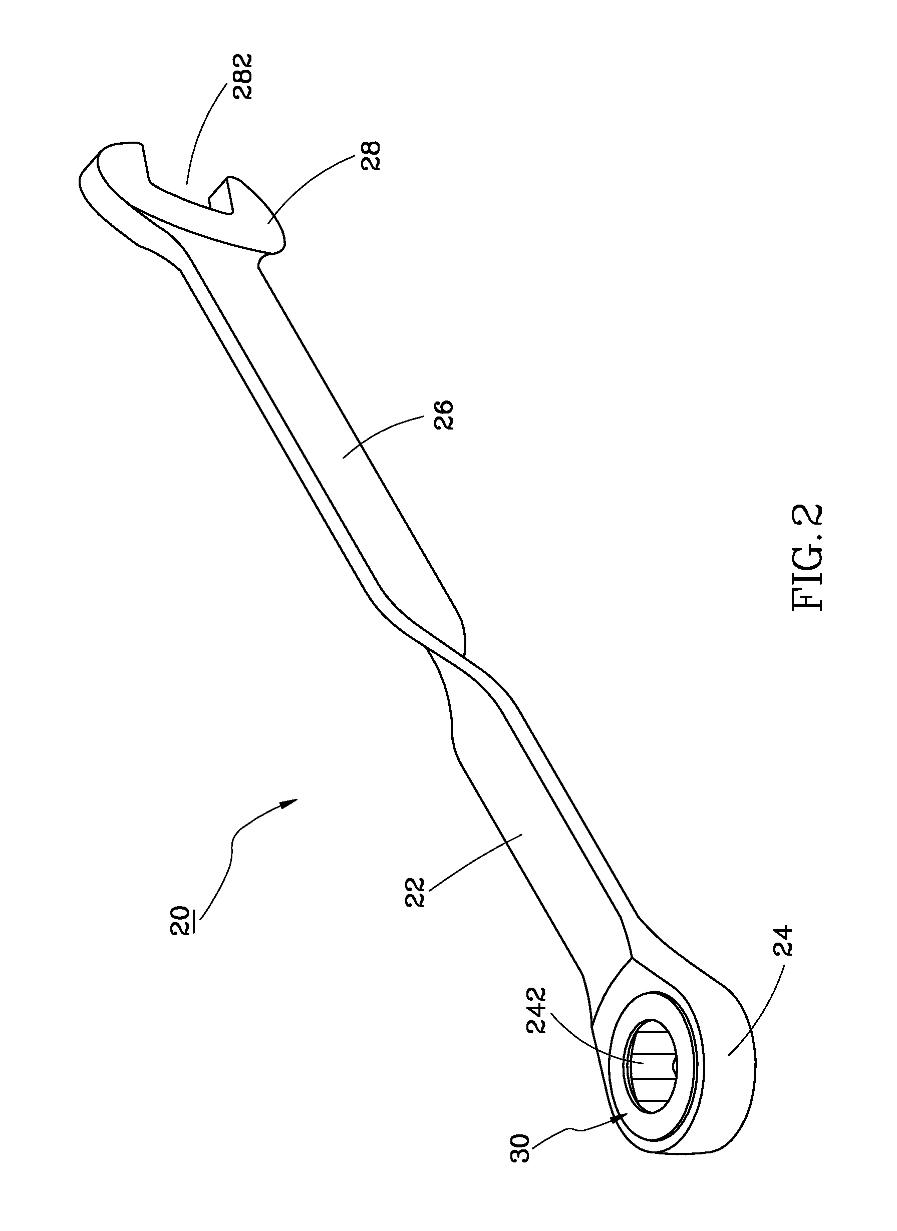
[0014]As shown in FIG. 2, a wrench 20 in accordance with a first preferred embodiment of the present invention comprises a first handle portion 22, a first wrench head 24, a second handle portion 26, and a second wrench head 28.

[0015]The first wrench head 24 is integrally connected with the first handle portion 22, and provided with a circular mounting hole 242 for installation of a racket wheel 30.

[0016]The second handle portion 26 is integrally connected with the handle portion 22, but twisted about a longitudinal axis of the body of the wrench 20 by a predetermined angle θ relative to the first handle portion 22. In this embodiment, the predetermined angle θ is 75 degrees, as shown in FIG. 3.

[0017]The second wrench head 28 is integrally connected with the second handle portion 26, and provided with a U-shaped socket 282 for engagement of a screw or nut.

[0018]By means of the aforesaid design, since a 75 degree angle is defined between the first handle portion 22 and the second han...


PUM


Abstract

A wrench includes a first handle portion, a first wrench head integrally connected with the first handle portion, a second handle portion integrally connected with the first handle portion, and a second wrench head integrally connected with the second handle portion. The second handle portion is twisted about a longitudinal axis of the wrench by a predetermined angle in a range of 75-85 degrees relative to the first handle portion, such that the wrench can offer a comfortable gripping feeling to the user by the aforesaid ergonomic twisted handle design.

Description

BACKGROUND OF THE INVENTION[0001]1. Field of the Invention[0002]The present invention relates generally to a wrench, and more specifically to a wrench having an ergonomic twisted handle design so as to improve user comfort.[0003]2. Description of the Related Art[0004]FIG. 1 shows a conventional wrench 10, comprising a first handle portion 12, a first wrench head 14 integrally connected with the first handle portion 12, a second handle portion 16 integrally connected with the first handle portion 12, and a second wrench head 18 integrally connected with the second handle portion 16. The second handle portion 16 is twisted about a longitudinal axis of the wrench 10 by an angle of 90 degrees relative to the first handle portion 12.[0005]According to the aforesaid design, when a user holds the first handle portion 12 to apply force to the second wrench head 18, or holds the second handle portion 16 to apply force to the first wrench head 14, the user may encounter difficulty in operatio...

Claims


Application Information

Patent Timeline
Patent Type & Authority Applications(United States)
IPC IPC(8): B25B23/16B25B13/46
CPCB25B13/08B25G1/105B25B13/461
Inventor CHANG, CHIH-MIN
Owner CHANG CHIH MIN
Why Eureka
Try Eureka