
Rock crusher attachment

a rock crusher and attachment technology, applied in the field of rock crushers, can solve the problems of lagging crushing power of the crusher mechanism, unable to crush the rock, and unable to meet the crushing requirements of hard rock applications,

Active Publication Date: 2012-01-26
JOY GLOBAL CANADA
View PDF3 Cites 41 Cited by
  • Summary
  • Abstract
  • Description
  • Claims
  • Application Information

AI Technical Summary

Problems solved by technology

Crushers using the known jaw actuating mechanisms described above have tended to have only partial success in the field.
While they tend to be generally effective at crushing softer rock in the range of 20,000 to 25,000 psi hardness, they have tended not to perform as well in applications requiring harder rock to be crushed.
In some cases where attempts were made to crush harder rock using such crushers, the crusher mechanism lacked the requisite crushing power to crush the rock, and stalled.
Worse still, in some extreme cases, the frames supporting the moving and fixed jaws flexed under the stress of crushing the harder rock, and failed.
Another drawback associated with these types of crushers is their inability to crush relatively large volumes of rock in a short period of time (i.e. that is more than 50 tons per hour), without substantially increasing the size of the crushing mechanism (and consequently, the cost of the crusher).
While some of the crushers of the type described above have this capability, adjusting the crushing mechanism to increase or reduce the crushing size can be a complicated, labour-intensive and time-consuming task, in some cases, requiring two or more workers several hours of work to complete.
Moreover, due to its complexity, such work tends not to be performed in the field and usually needs to be carried out at a maintenance / repair facility.

Method used


Image

  • Rock crusher attachment
  • Rock crusher attachment
  • Rock crusher attachment

Examples


Embodiment Construction

[0056]The description, which follows, and the embodiments described therein are provided by way of illustration of an example, or examples of particular embodiments of principles and aspects of the present invention. These examples are provided for the purposes of explanation and not of limitation, of those principles of the invention. In the description that follows, like parts are marked throughout the specification and the drawings with the same respective reference numerals.

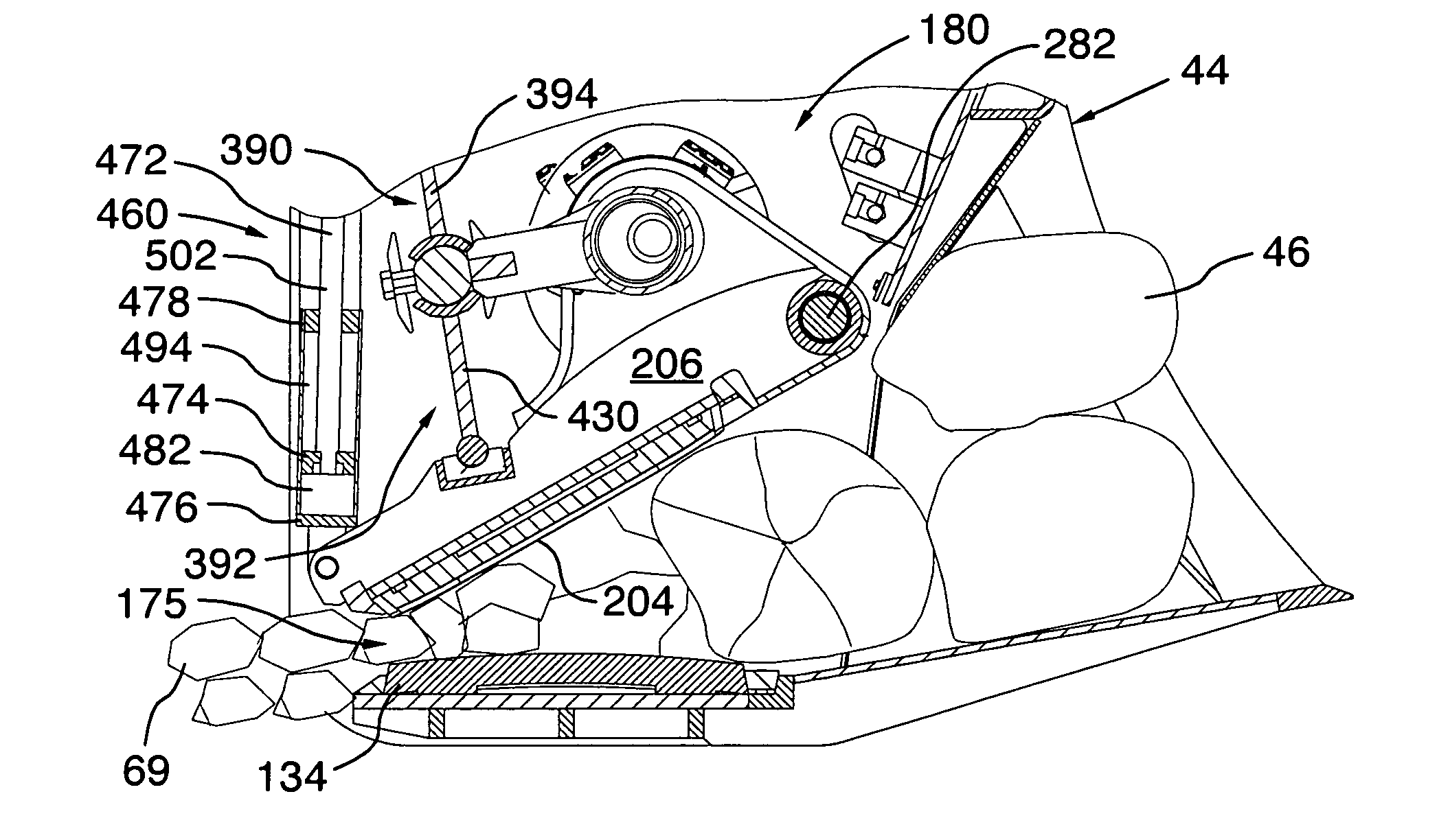
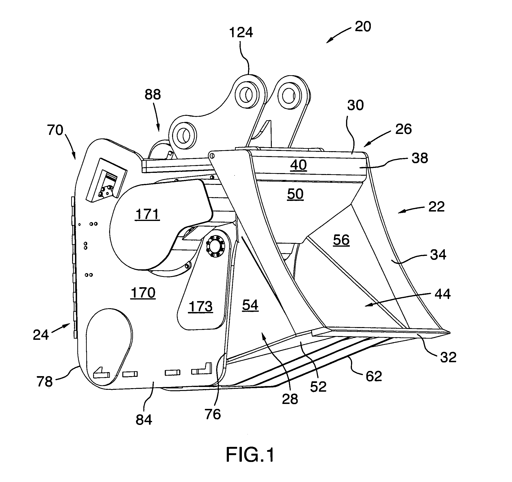
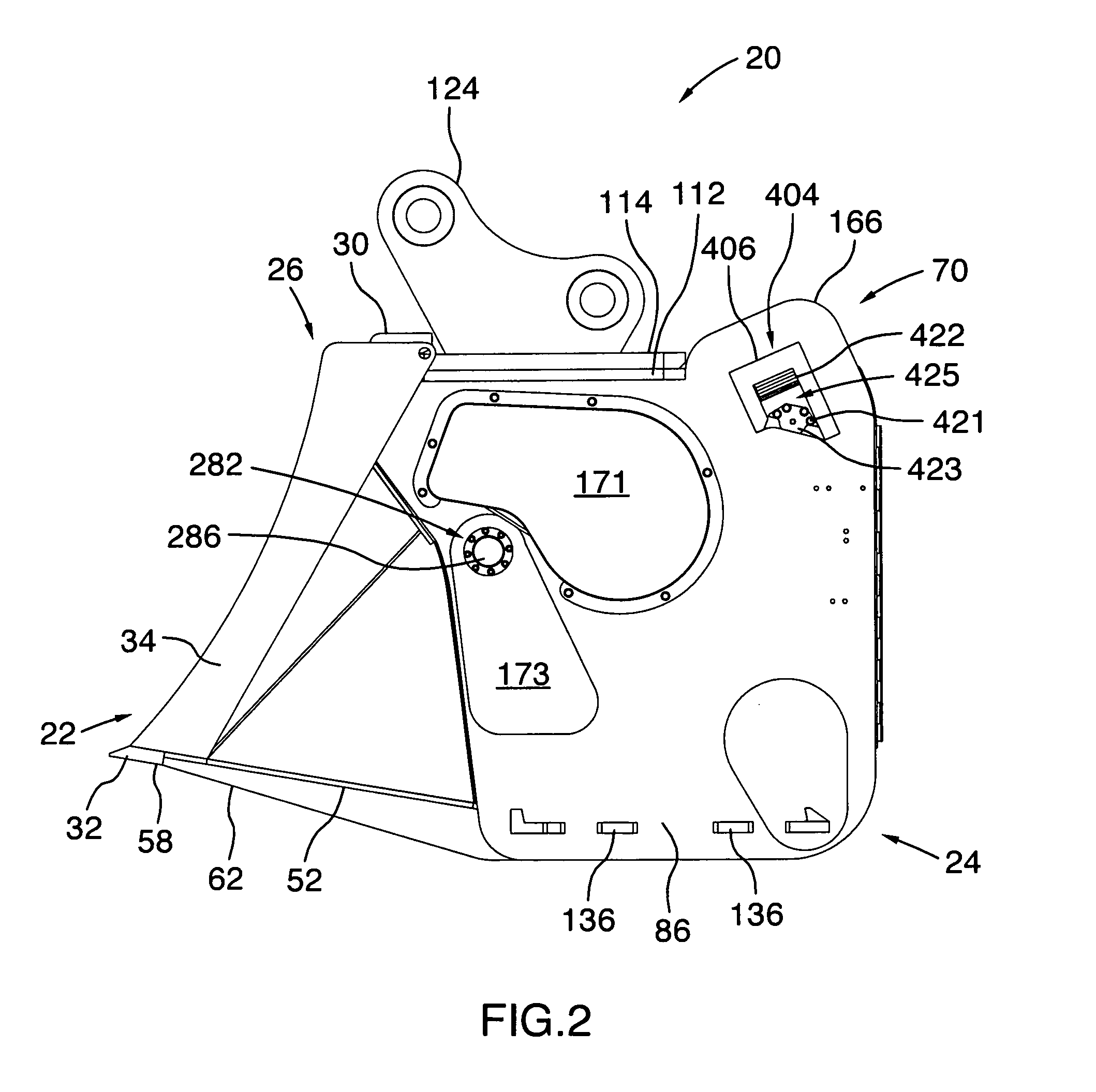
[0057]Referring to FIGS. 1 to 6, there is shown a rock crusher attachment designated generally with reference numeral 20. The rock crusher attachment 20 is designed to be suspended from or carried on the boom (not shown) of an earthmoving vehicle, such as an excavator, a backhoe, a loader, or the like. The rock crusher attachment 20 has a front bucket portion 22 and a rear crusher portion 24 joined thereto. The front bucket portion 22 is provided with a frame 26 welded to a bucket body 28. The frame 26 includ...


PUM


Abstract

The present invention relates to the field of rock crushers, in particular, rock crusher attachments for earth moving equipment or the like. The rock crusher attachment includes a front bucket portion configured for scooping rocks to be crushed and a rear crusher portion connected to and in communication with the rear of the bucket portion. The crusher portion includes a housing and a crushing assembly accommodated within the housing. The housing including a pair of spaced apart side panels. The crushing assembly has a lower jaw fixed between the side panels of the housing and an upper movable jaw mounted opposite and spaced apart from the lower jaw. The upper movable jaw assembly includes a support, an upper jaw plate attached to the underside of the support and a jaw-actuating drive assembly operable to urge the upper movable jaw assembly to move between an open jaw setting and a closed jaw setting. The support is pivotally connected between the side panels adjacent the front of the housing. The jaw-actuating drive assembly includes at least one motor carried by the support. The at least one motor is urged to move along with the upper movable jaw assembly relative to the lower jaw, when the crusher assembly is actuated.

Description

FIELD OF THE INVENTION[0001]The present invention relates to the field of rock crushers, in particular, rock crusher attachments for earthmoving vehicles or the like.BACKGROUND OF THE INVENTION[0002]Rotary crushers are used in a variety of mining applications as well as in construction / demolition settings. A typical rotary crusher has a housing made of steel plate, a first fixed jaw and a second movable jaw positioned facing each other inside the housing. When the rotary crusher is actuated, the second movable jaw is urged to move between an open jaw setting (where the gap between the first end of the second movable jaw and the fixed jaw is at its greatest) and a closed jaw setting (where the gap between first end of the second movable jaw and the fixed jaw is at its smallest). When the second movable jaw in the closed jaw setting, a crushing force is delivered to the rock held between the jaws.[0003]Different mechanisms have been used to actuate the movable jaw. One known mechanism...

Claims


Application Information

Patent Timeline
IPC IPC(8): B02C1/04B02C21/02B02C23/16
CPCB02C1/10B02C1/04E02F3/965E02F3/407
Inventor GERVAIS, JOSEPH LUCIEN FERNANDDICKSON, NICHOLAS SCOTT
Owner JOY GLOBAL CANADA
Features
  • Generate Ideas
  • Intellectual Property
  • Life Sciences
  • Materials
  • Tech Scout
  • Unparalleled Data Quality
  • Higher Quality Content
  • 60% Fewer Hallucinations
Learn More