Method for forming a patterned coating

Inactive Publication Date: 2012-02-09
HON HAI PRECISION IND CO LTD
View PDF0 Cites 4 Cited by
  • Summary
  • Abstract
  • Description
  • Claims
  • Application Information

AI Technical Summary

Problems solved by technology

However, edges of the masked regions may not be sharp because the liquid masking material used may seep under the edges of the masking material.

Method used


Image

  • Method for forming a patterned coating
  • Method for forming a patterned coating
  • Method for forming a patterned coating

Examples


Embodiment Construction

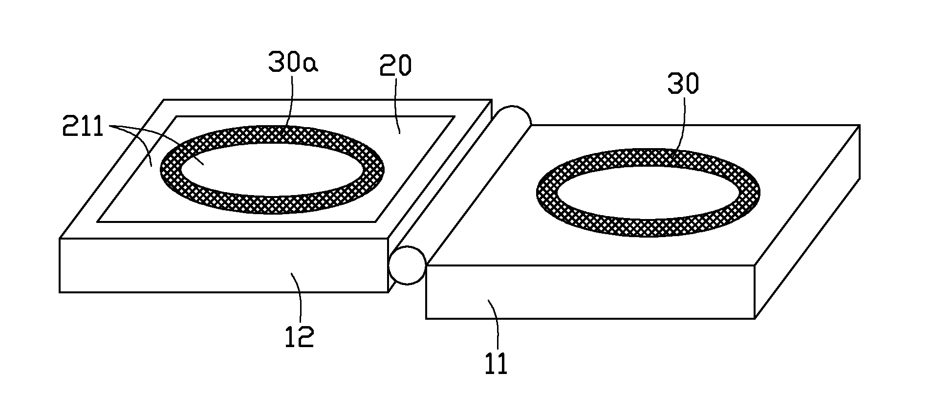
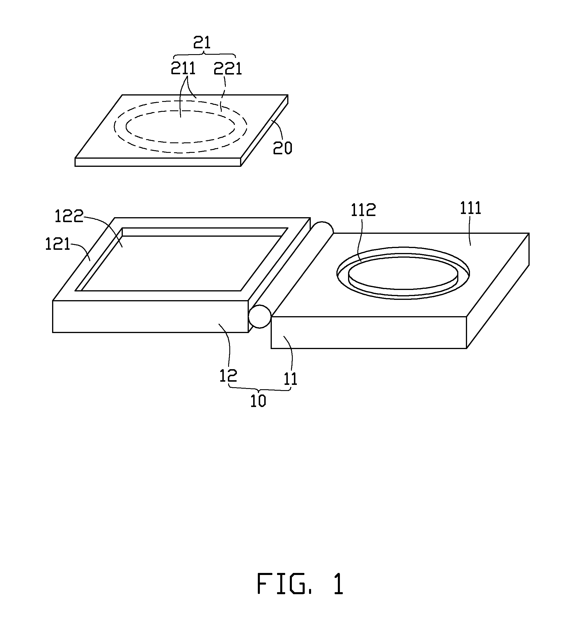
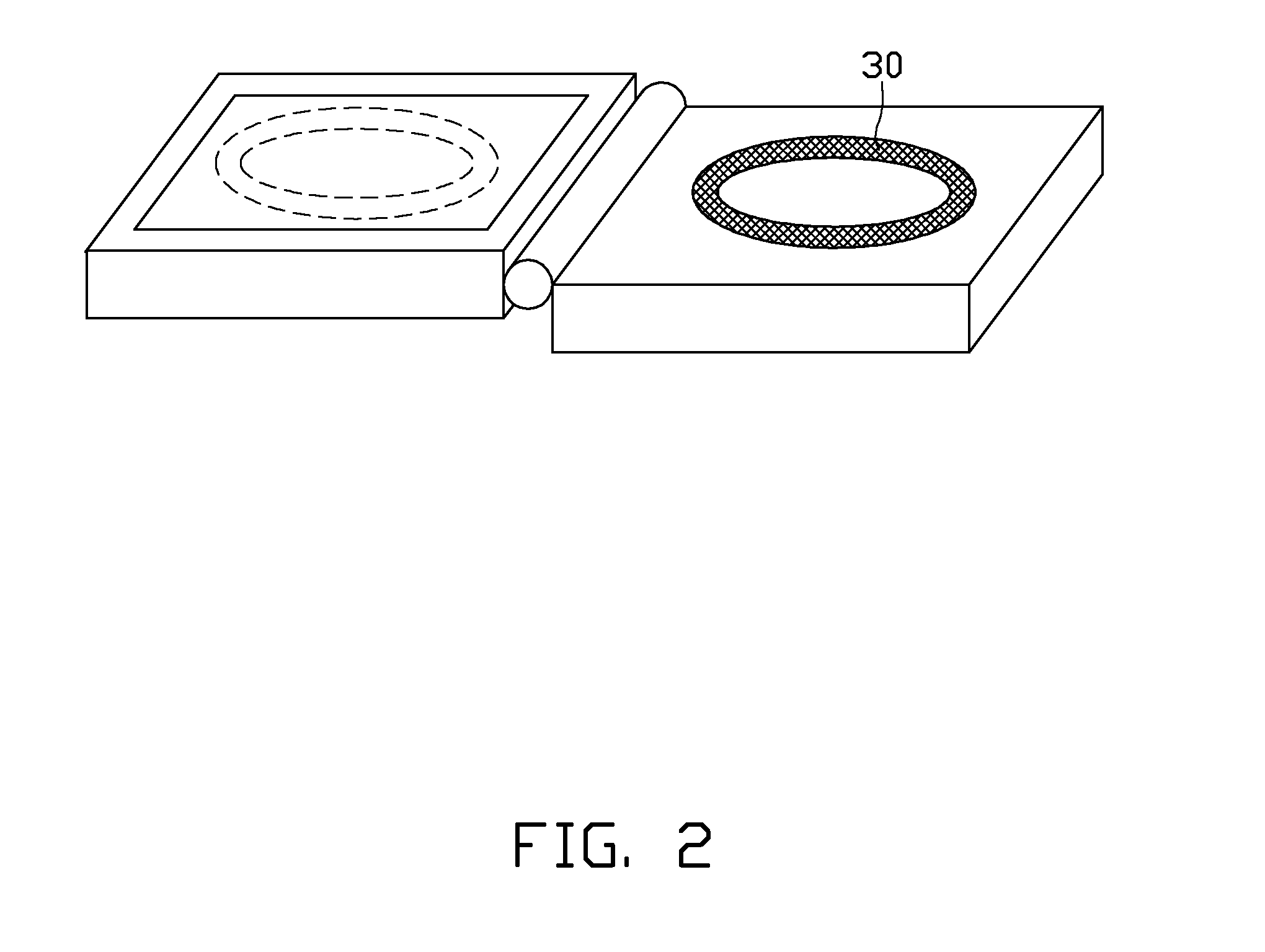
[0012]FIG. 1 shows a masking fixture 10 and a workpiece 20 provided in accordance with an exemplary embodiment. The workpiece 20 can be glass, silicon, quartz, carborundum, plastic or stainless steel. In the present embodiment, the workpiece 20 is a plastic plate used as part of an encasing for portable computer. The workpiece 20 includes an outer surface 21. The outer surface 21 includes a flat coating region 211 and a flat pattern region 221 for forming a graphic. In the present embodiment, as shown with dashed line in FIG. 1, the pattern region 221 is ring-shaped. The workpiece 20 is detachably fixed in the masking fixture 10.

[0013]The masking fixture 10 includes a liquid masking applicator 11 and a workpiece holder 12 pivotably connected to the liquid masking applicator 11. The liquid masking applicator 11 has a masking surface 111. A groove 112 having the same outline shape as the pattern region 221 is defined in the masking surface 111. The liquid masking applicator 11 is resi...


PUM


Abstract

A method for forming a coating on a plate-shaped workpiece is disclosed. In the method, a plate-shaped workpiece and a masking fixture are provided. The workpiece includes a surface including a coating region and a pattern region. The masking fixture includes a resilient liquid masking applicator having a groove. An outline shape of the groove conforms to the pattern region. The groove is filled with liquid masking material. The workpiece is pressed onto the liquid masking applicator with the pattern region aligned with the groove. The liquid masking material is solidified thereby the solidified liquid masking material is attached to the pattern region of the workpiece. A coating is formed on the coating region. The solidified liquid masking material is removed from the workpiece.

Description

BACKGROUND[0001]1. Technical Field[0002]The present disclosure relates to surface coating technology, and particularly, to a coating method for forming a patterned film layer on an outer surface of a workpiece.[0003]2. Description of Related Art[0004]Often graphics, such as logos, are formed on electronic products, such as computers, cell phones, and digital cameras by masking. However, edges of the masked regions may not be sharp because the liquid masking material used may seep under the edges of the masking material. Thus, a coating method is desired to overcome the limitations described.BRIEF DESCRIPTION OF THE DRAWINGS[0005]Many aspects of the present method can be better understood with reference to the following drawings. The components in the drawings are not necessarily drawn to scale, the emphasis instead being placed upon clearly illustrating the principles of the presentment method. Moreover, in the drawings, like reference numerals designate corresponding parts througho...

Claims


Application Information

Patent Timeline
IPC IPC(8): B05D1/32
CPCB05B15/045B05D1/322B05B12/20
Inventor WANG, CHUNG-PEI
Owner HON HAI PRECISION IND CO LTD
Why Eureka
Try Eureka