Compression sleeve with improved position retention

a compression sleeve and position retention technology, applied in the field of compression devices, can solve the problems of ineffective compression therapy, discomfort, and difficulty in patient movemen

Active Publication Date: 2012-03-15
KPR U S LLC
View PDF29 Cites 57 Cited by
  • Summary
  • Abstract
  • Description
  • Claims
  • Application Information

AI Technical Summary

Problems solved by technology

This can be very difficult when the patient moves, such as by walking, sitting, standing, and rolling over.
The garments tend to loosen around the body part or slide down the body part causing misalignment of inflatable bladders on the garment with respect to the body part, which may result in ineffective compression therapy and / or discomfort.

Method used


Image

  • Compression sleeve with improved position retention
  • Compression sleeve with improved position retention
  • Compression sleeve with improved position retention

Examples


second embodiment

[0032]In a second embodiment, an insert 90′ (FIG. 9) comprises a bridge having leg portions 106′ having no reduced width sections. The insert 90′ otherwise functions substantially the same as insert 90.

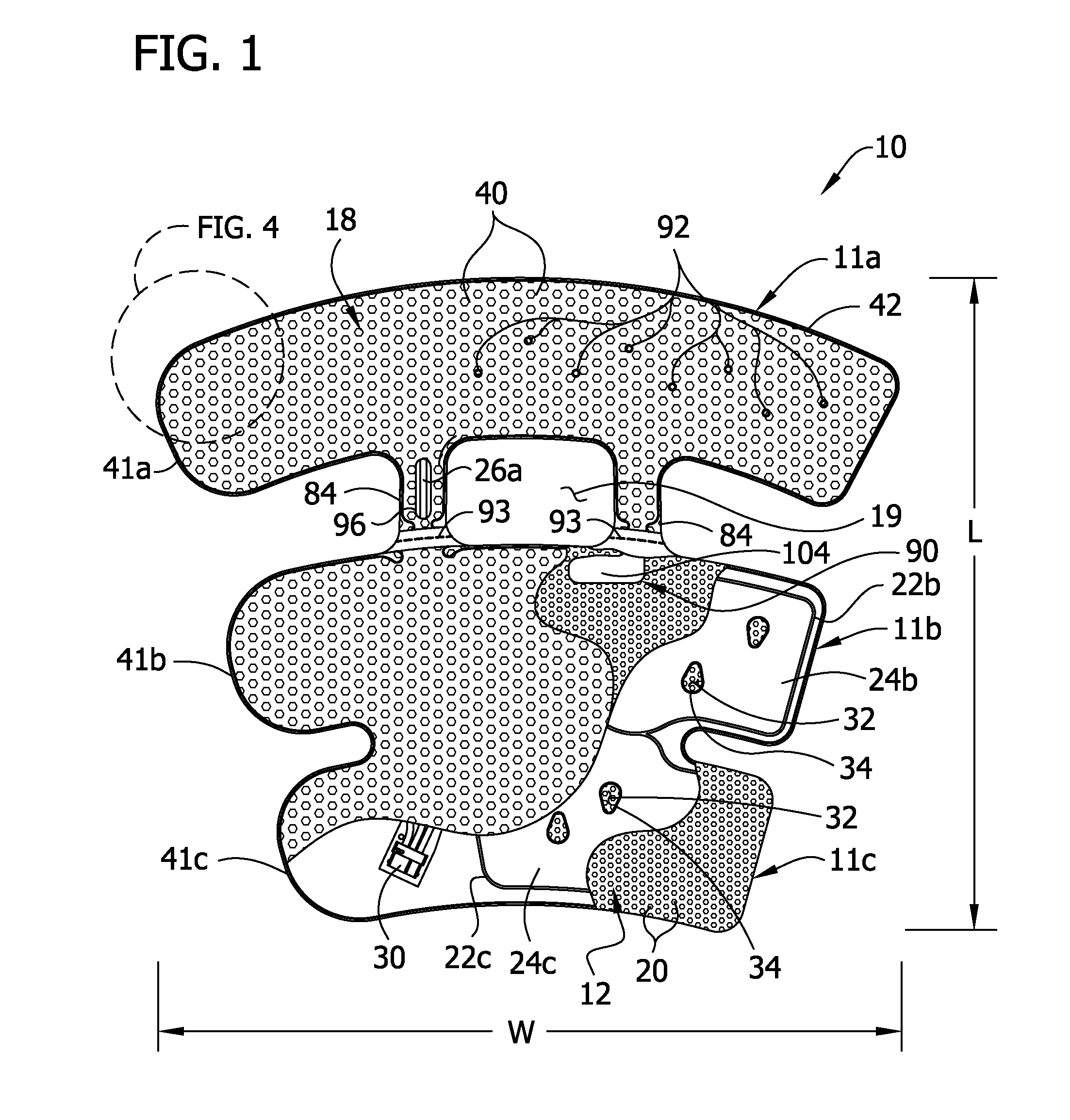
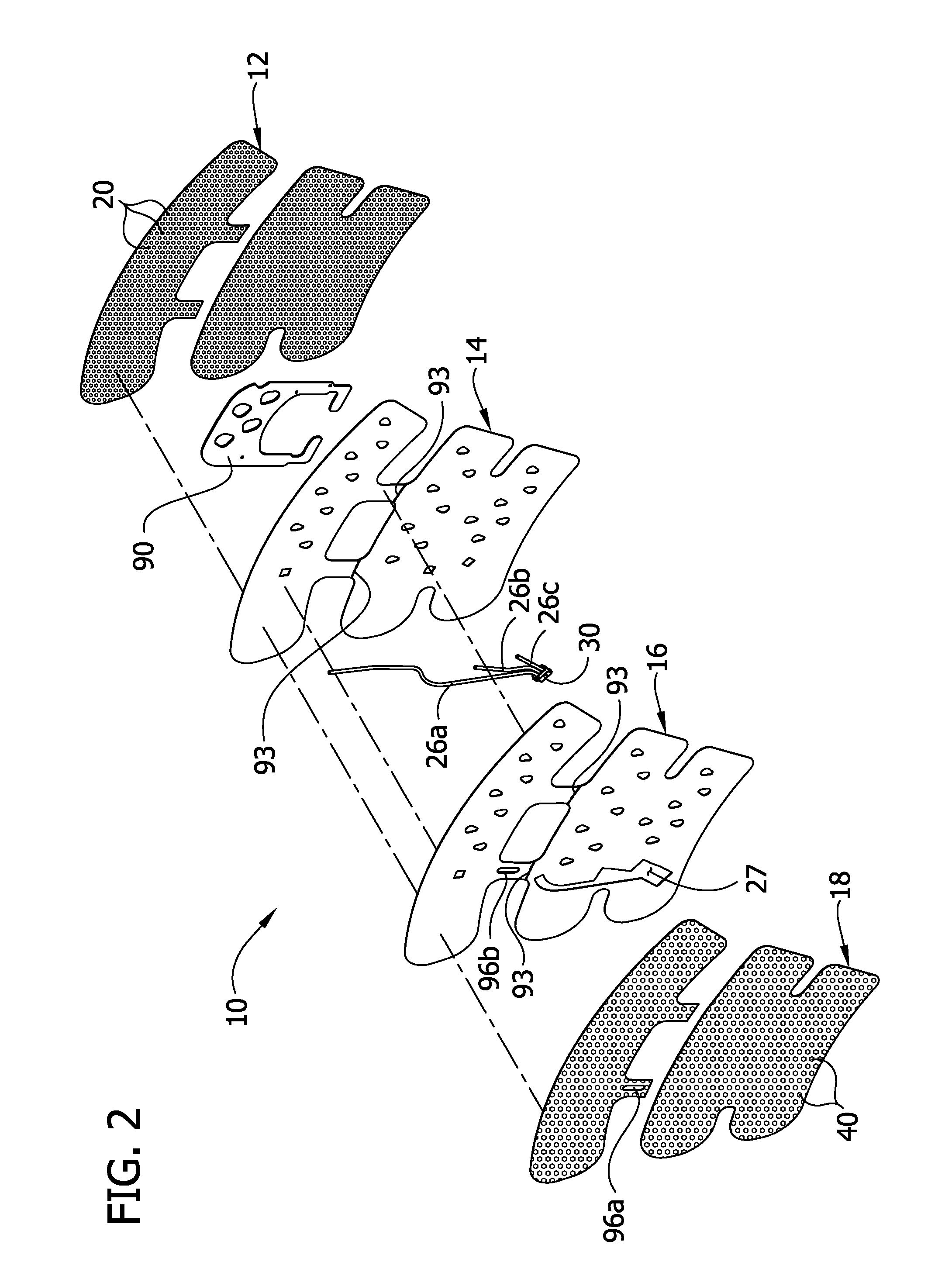
[0033]In the illustrated embodiment, the thigh section 11a is removable from the remainder of the sleeve 10 to convert the sleeve from thigh length to knee length. In particular, the proximal portion of the sleeve 10 that includes the proximal bladder 24a and the bridge members 84 are removable from the remainder of the sleeve. Tear lines comprising perforation lines 93 in the intermediate layers 14, 16, extend transversely across the intermediate layers adjacent to where the bridge members 84 join thigh section 11a to the calf and ankle sections 11b, 11c. In a preferred embodiment, the removal is destructive and permanent. It is understood that the sleeve may include one tear line or more than two tear lines within the scope of the invention. It is also understood that the shapes of ...

first embodiment

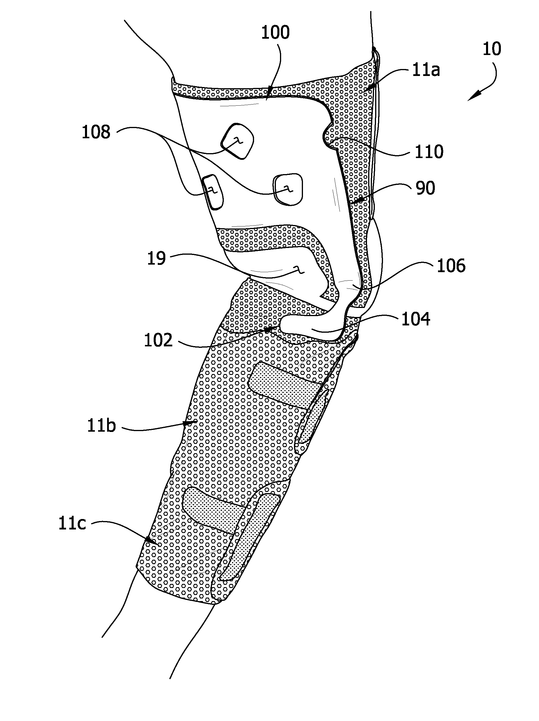
[0040]Similarly, as shown in the insert 90, the leg portions 106 have the reduced width section 112 which makes it easier to pull the leg portions 106 and foot portions 104 from the knee section 11b of the sleeve 10. In addition to accommodating the terminal securement lines 95a, 95b, the reduced width portion 112 reduces the amount of material of the insert 90 at and below the bridge members 84. This construction makes it easier to remove the leg portions 106 and foot portions 104, from the knee section 11b of the sleeve 10. Thus, if the thigh section 11a and bridge members 84 are removed from the garment 10, the perforations 93 (see, FIG. 2a) are torn part way. The reduced width section 12 and extensions 104 are pulled out from the calf section 11b, and tearing of the perforation 93 is completed to separate the thigh section 11a and bridge members 84 from the remainder of the garment 10. Other ways of achieving separation are contemplated. For example, the leg portions of an inser...


PUM


Abstract

A compression garment having first and second sections includes a stay up device for supporting the compression garment in position on the body. The stay up device is constructed to operatively engage a portion of the body to positively locate the stay up device, and thereby the garment relative to the body.

Description

FIELD OF THE INVENTION[0001]The present invention is directed generally to a compression device for applying compression therapy to a body part of a wearer, and more particularly to a compression device with an improved capability to retain its position on the body part.BACKGROUND OF THE INVENTION[0002]Compression garments for applying intermittent compression therapy to a body part (e.g., a limb such as a leg) have many applications, including deep vein thrombosis prophylaxis, edema prevention, and aiding in wound healing. It is sometimes desirable to provide active compression therapy during and after surgical procedures. The performance of these compression garments is sensitive to the ability of the garment to retain its initial fit and position around the body part. This can be very difficult when the patient moves, such as by walking, sitting, standing, and rolling over. The garments tend to loosen around the body part or slide down the body part causing misalignment of inflat...

Claims


Application Information

Patent Timeline
Patent Type & Authority Applications(United States)
IPC IPC(8): A61B17/00
CPCA61F13/06A61F13/00995A61F13/085A61H2201/1697A61F2013/00174A41D1/00A61F5/30A61H9/0092A61B17/12A61B17/00A61H9/0078
Inventor AVITABLE, RAYMOND C.KANTER, ROSSBROOKS, DEL
Owner KPR U S LLC
Why Eureka
Try Eureka