Image forming apparatus

a technology of forming apparatus and image, which is applied in the direction of electrographic process apparatus, instruments, optics, etc., can solve the problems of increasing the amount of toner, increasing the risk of fixing tacking, and slow drying speed of toner, so as to achieve efficient drying of images, reduce printing efficiency and economic efficiency

Active Publication Date: 2012-03-22
KONICA MINOLTA BUSINESS TECH INC
View PDF4 Cites 19 Cited by
  • Summary
  • Abstract
  • Description
  • Claims
  • Application Information

AI Technical Summary

Benefits of technology

[0017]The present invention is provided in view of the above problems, and aims to provide an image forming apparatus that (i) can efficiently dry an image on a recording sheet that is to be ejected onto the ejected-sheet tray without reduction of printing efficiency and economic efficiency and (ii) does not require rearrangement of an order of recording sheets that are ejected onto the ejected-sheet tray.

Problems solved by technology

A problem that recording sheets adhere to each other with toner is normally called “fixing tacking”.
This is because a drying speed of toner becomes slow.
Furthermore, when a basis weight of a recording sheet is large, fixing tacking is more likely to occur since toner on an upper recording sheet is pressed with a high pressure against a recording sheet that is positioned under the upper recording sheet with its own weight.
Also, when a coverage ratio that is a ratio of a toner image to a surface of a recording sheet is high, an amount of toner is large and therefore fixing tacking is more likely to occur.
Moreover, when a speed (system speed) of transportation of recording sheets becomes high in successively performing image formation, intervals of transportation of recording sheets ejected onto the ejected-sheet tray become short.
As a result, fixing tacking is more likely to occur.
This results in reduction of printing efficiency.
Moreover, if an amount of air moved by the blast fan is increased so as to dry ink faster, consumed electric power increases, and at the same time, a loud noise might occur.
However, with such a structure, an order of recording mediums ejected onto the ejected-sheet tray changes, and accordingly a user has to rearrange the order of the ejected recording mediums.

Method used


Image

  • Image forming apparatus
  • Image forming apparatus
  • Image forming apparatus

Examples


Embodiment Construction

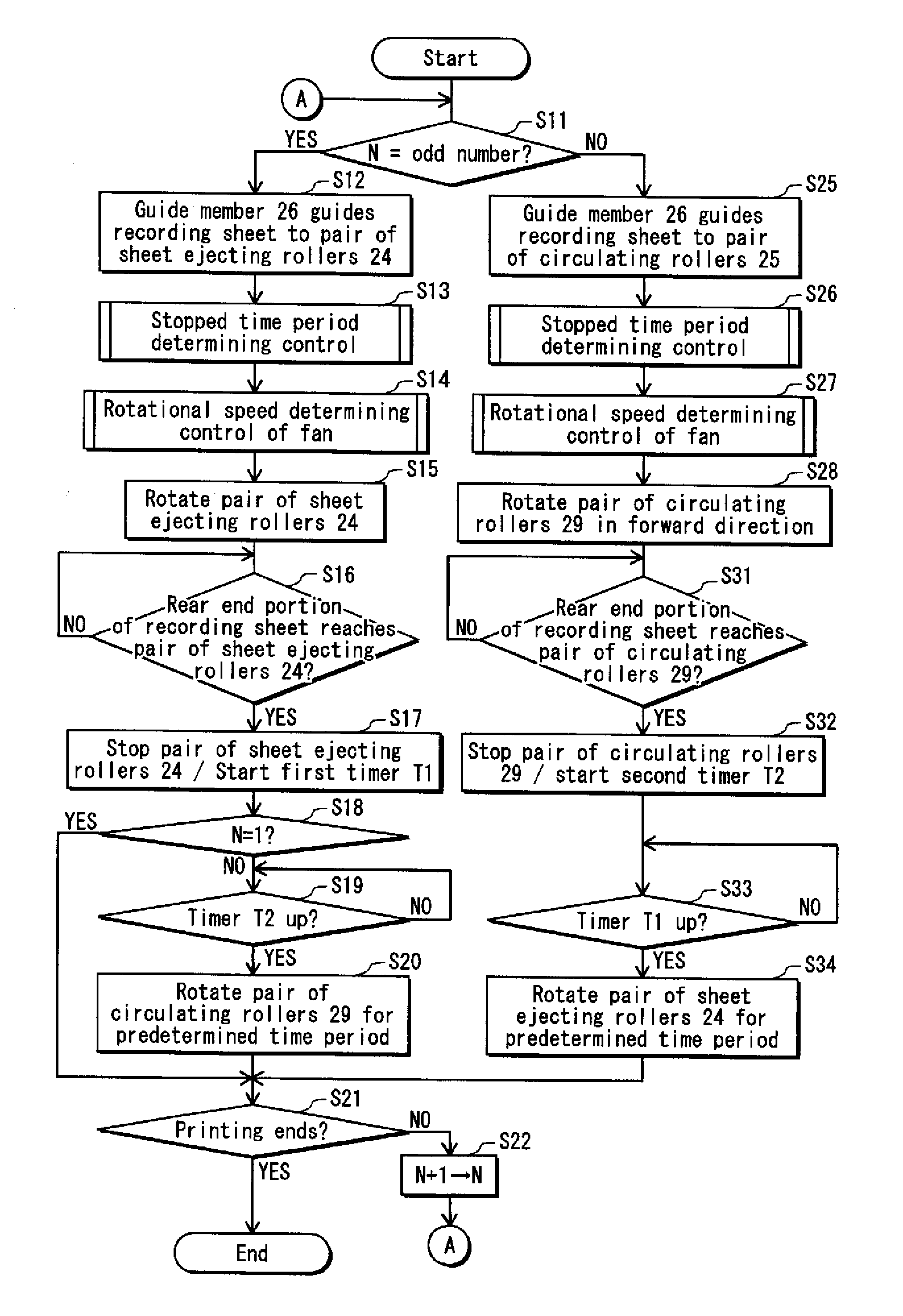
[0038]The following describes an embodiment of an image forming apparatus pertaining to the present invention.

[0039]

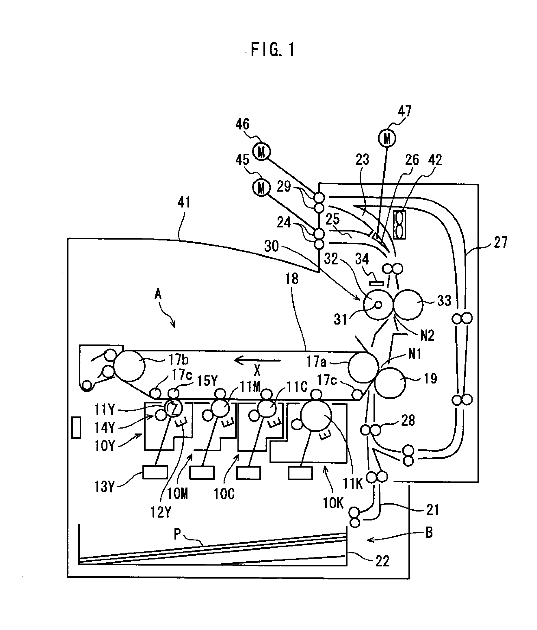
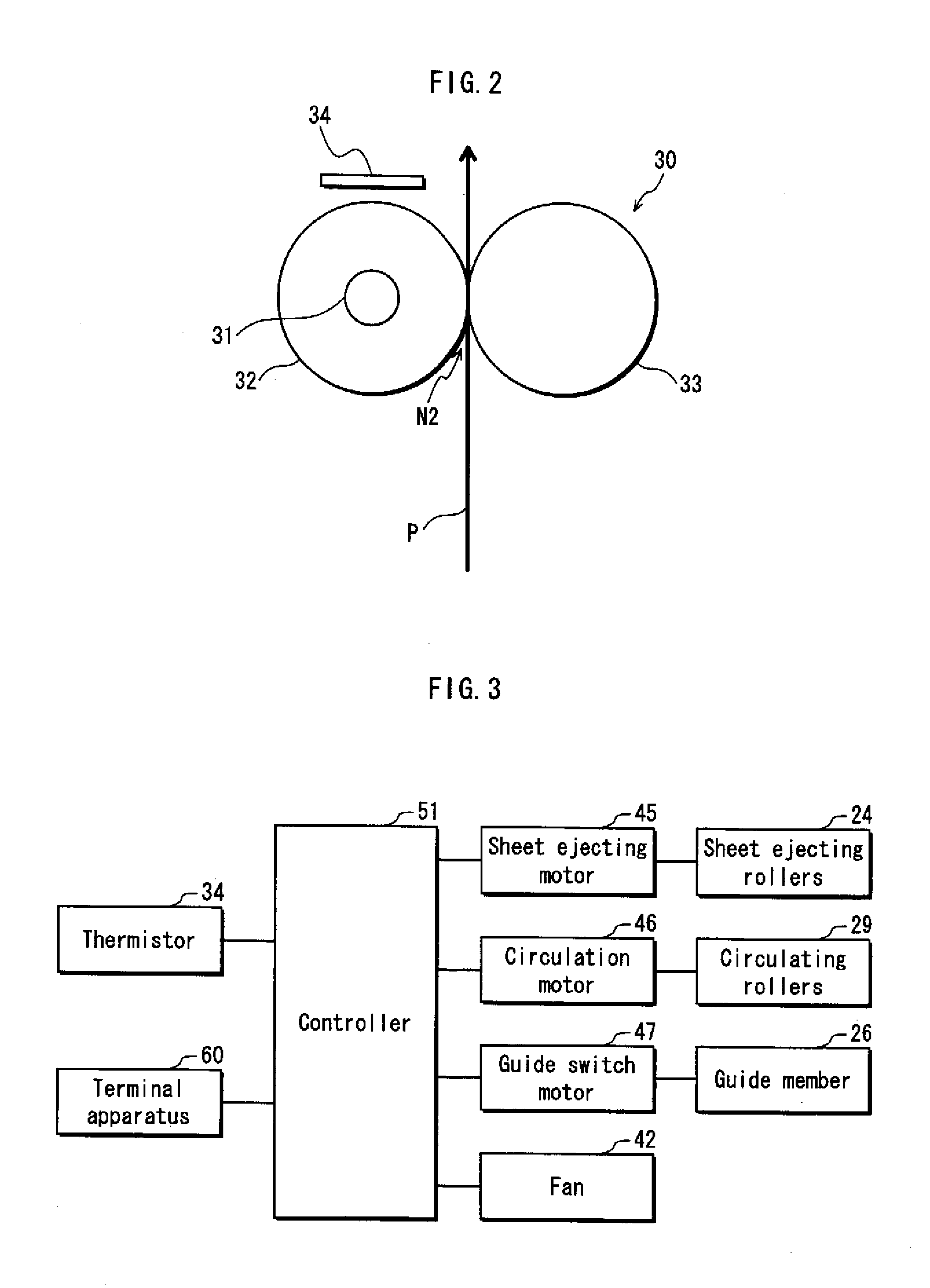
[0040]FIG. 1 is a schematic view showing a schematic structure of a tandem type color digital printer (hereinafter, simply referred to “printer”), which is an example of the image forming apparatus pertaining to the embodiment of the present invention. Such a printer forms a toner image on a recording sheet by a known electrophotographic method based on image data and the like that are input from an external terminal apparatus and the like via a network (e.g., LAN).

[0041]The printer includes an image processing unit A that performs image formation (printing) and a paper feeder B provided under the image processing unit A. At a substantially central portion of the image processing unit A in a vertical direction, an intermediate transfer belt 18 having an elongated revolving movement area in a horizontal direction is provided. The intermediate transfer 18 winds around a ...


PUM


Abstract

An image forming apparatus comprises: a pair of first sheet ejecting rollers and a pair of second sheet ejecting rollers that eject a sheet on which an image is formed; a guide member that guides the sheet to the pair of first sheet ejecting rollers or the pair of second sheet ejecting rollers; a controller that performs control so that, while a sheet that is to be ejected by the pair of first sheet ejecting rollers onto an ejected-sheet tray is being held by the pair of first sheet ejecting rollers in a stopped state, the pair of second sheet ejecting rollers is in a stopped state and hold an immediately subsequent sheet above the ejected-sheet tray; and a fan that moves air toward the sheet held by the pair of first sheet ejecting rollers and the immediately subsequent sheet held by the pair of second sheet ejecting rollers.

Description

[0001]This application is based on application No. 2010-210917 filed in Japan, the contents of which are hereby incorporated by reference.BACKGROUND OF THE INVENTION[0002](1) Field of the Invention[0003]The present invention relates to an image forming apparatus that forms an image on recording sheets, and in particular to a drying technique to dry a developer such as toner and ink that constitute the image formed on the recording sheets.[0004](2) Description of the Related Art[0005]An image forming apparatus (e.g., a copying machine or a printer) that forms a toner image by an electrophotographic method normally transfers the toner image formed on a photosensitive drum onto a recording sheet, and then fixes the toner image by a fixing device. The fixing device heats the toner image on the recording sheet and applies pressure on the recording sheet to fix the toner image. The recording sheet on which the toner image has been fixed is ejected on an ejected-sheet tray.[0006]The record...

Claims


Application Information

Patent Timeline
Patent Type & Authority Applications(United States)
IPC IPC(8): G03G15/00G03G21/20
CPCG03G2215/0132G03G15/6573
Inventor MURAKAMI, YUSUKENOZAWA, SHIGEKI
Owner KONICA MINOLTA BUSINESS TECH INC
Why Eureka
Try Eureka