Multi-Canted Coils, Tubes, and Structures

a multi-canted coil and coil technology, applied in the direction of springs/dampers, wound springs, mechanical equipment, etc., can solve the problems of rubbing or scrubbing damage to the contact surface, and achieve the effect of reducing and/or eliminating any horizontal forces or moments

Inactive Publication Date: 2012-04-26
VELOCE LABS
View PDF13 Cites 22 Cited by
  • Summary
  • Abstract
  • Description
  • Claims
  • Application Information

AI Technical Summary

Benefits of technology

[0011]A coil comprising a plurality of interconnected individual coils is formed along a length of a coil axis, wherein each of the individual coils comprising the coil has two or more cants formed therein, and wherein the cants formed therein are configured to exhibit a load-deflection force when each individual coil is compressed. Tubes and other designs are configured to exert load-deflection forces when compressed through multi-canted portions, legs or extensions from the core design. These multi-canted coils, tubes, and designs are configured to substantially reduce and / or eliminate any horizontal forces or moments created when a downward force is applied to the multi-canted portions of each.

Problems solved by technology

However, even with the advancement of load deflection designs and in particular perpendicular load deflection, there is a still a need for improving a coil design to reduce wear against contact surfaces, and to reduce sliding and rotation, which often results in rubbing or scrubbing damage to a contact surface.

Method used


Image

  • Multi-Canted Coils, Tubes, and Structures
  • Multi-Canted Coils, Tubes, and Structures
  • Multi-Canted Coils, Tubes, and Structures

Examples


Embodiment Construction

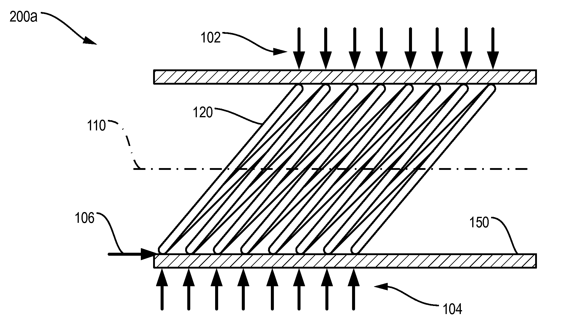
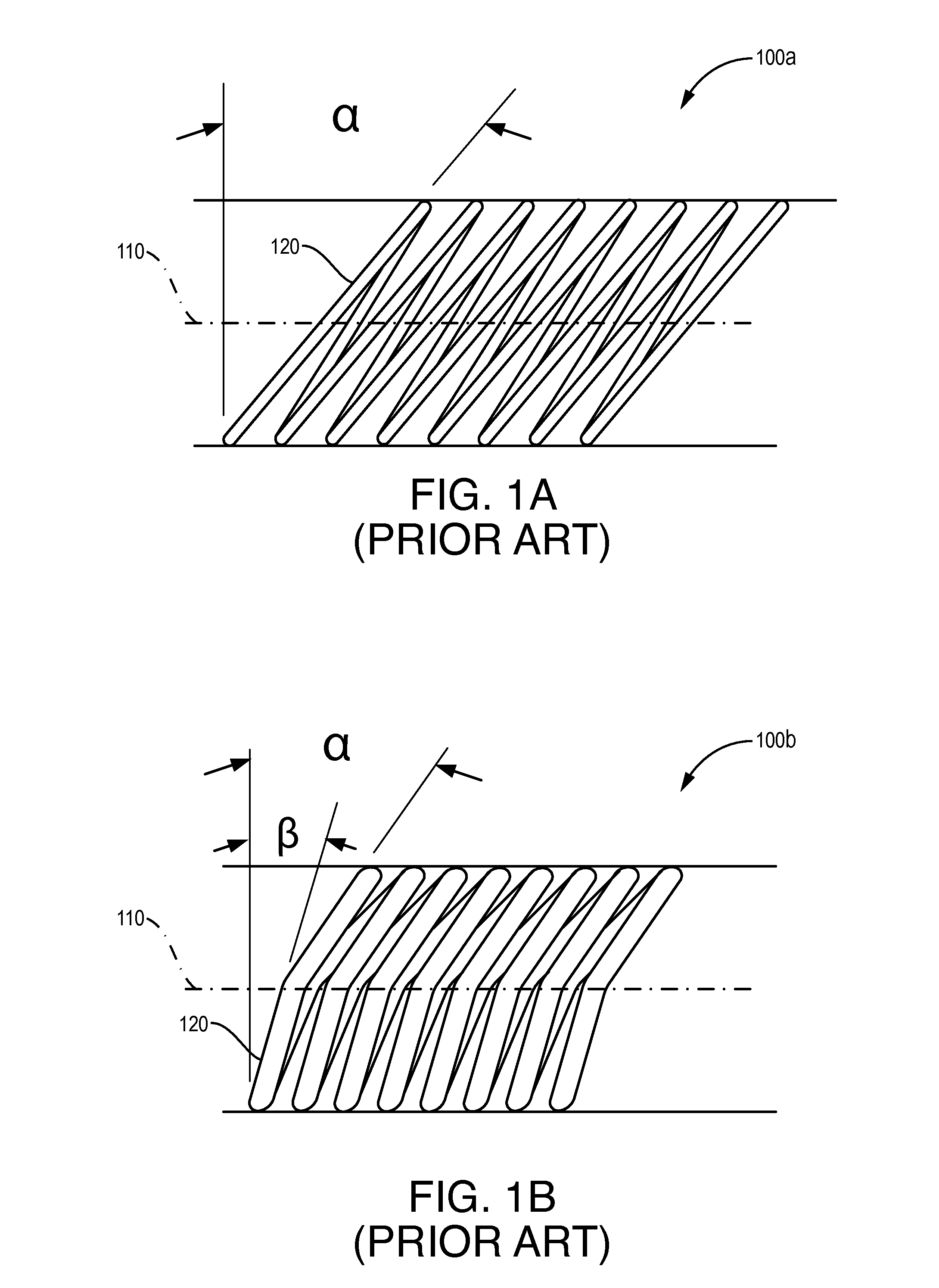
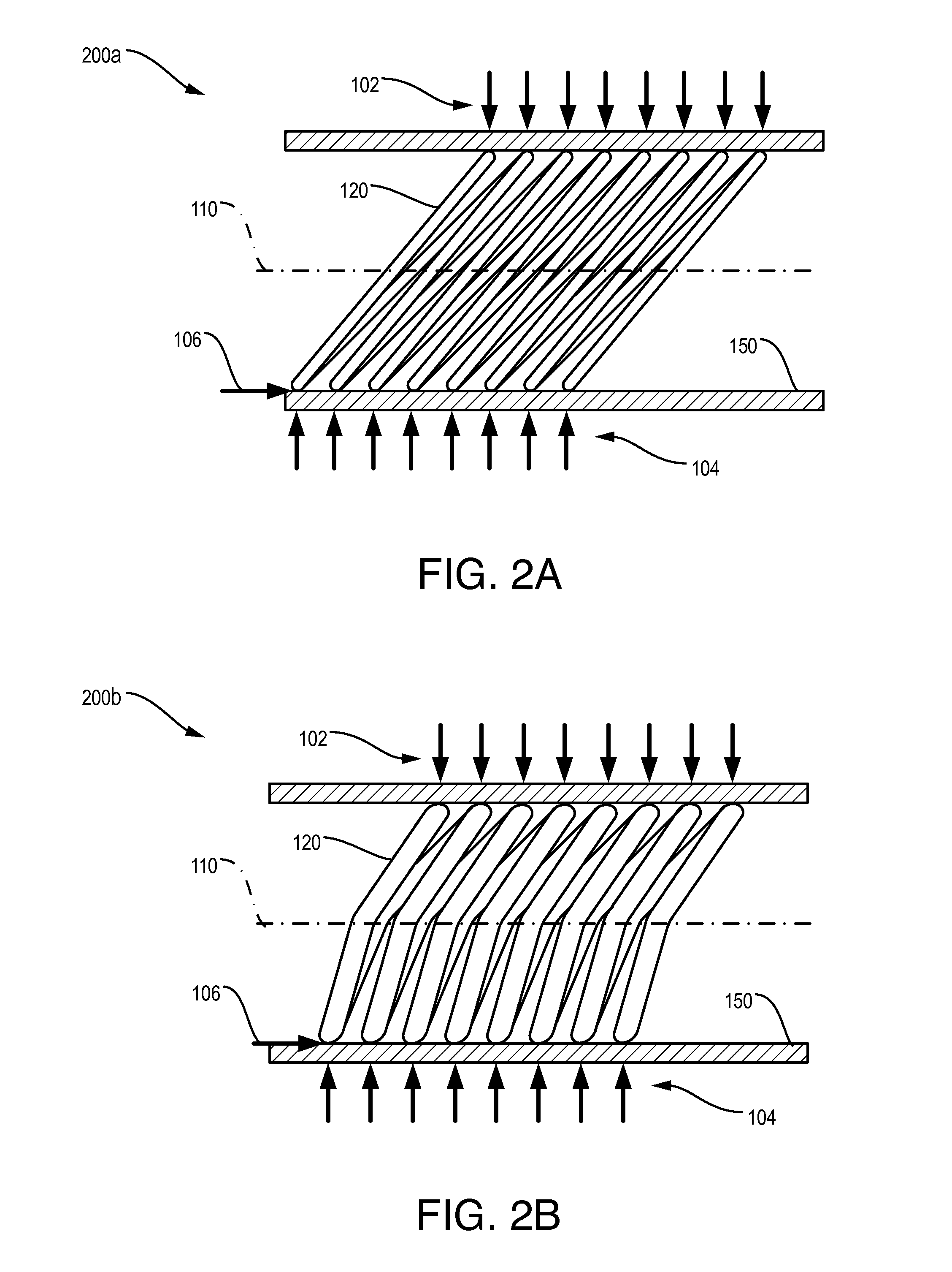
[0034]When a round coil spring is canted, the geometry of the coil is changed and takes on a slanted appearance, such as that shown in FIGS. 1A-B. For purposes of this application, a cant refers to a bend, slant, arc or curve along a portion of a coil, rung, leg or other part of a spring or tube wherein an angle, slant, arc, or tilted appearance is formed. A cant may have varying radii such as a curve with varying radii. The cant may be formed with respect to a contact surface, centerline, coil axis, and / or length of a coil or tube. For example, in prior art shown in FIG. 1A, a single-canted portion of each coil having angle α is shown to emanate from the bottom contact surface. However, it may also be said the single cant is formed about the coil axis 110. FIG. 1B illustrates another prior art design where a coil may have varying or variable cants along a portion of an individual coil wherein one portion is canted or formed at angle β and another portion thereafter is canted at ang...


PUM


Abstract

Coil, tube, and other structures configured with a plurality of individual coils, internal structures, legs or extensions with each having multiple cants per coil, internal structure, leg or extension, and wherein the cants formed therein allow for a load-deflection force when each is compressed. In addition, any horizontal or moment forces are substantially reduced and / or eliminated when a downward vertical force is applied, as minimal or no torsion is created in the individual coils, legs or extensions.

Description

CROSS-REFERENCE TO RELATED APPLICATIONS[0001]This application claims priority under 35 U.S.C. §119 to the following U.S. Provisional Patent Application, which is hereby incorporated by reference in its entirety: U.S. Ser. No. 61 / 405,295 filed Oct. 21, 2010.THIRD PARTY RIGHTS[0002]This invention was made with government support under NASA prime contract NNC06BA07B. The Government has certain rights in the invention.COPYRIGHT STATEMENT[0003]A portion of the disclosure of this patent application document contains material that is subject to copyright protection including the drawings. The copyright owner has no objection to the facsimile reproduction by anyone of the patent document or the patent disclosure as it appears in the Patent and Trademark Office file or records, but otherwise reserves all copyright rights whatsoever.BACKGROUND OF THE INVENTION[0004]1. Field of the Invention[0005]The present embodiments relate generally to mechanical springs, tubes, and other structures utiliz...

Claims


Application Information

Patent Timeline
Patent Type & Authority Applications(United States)
IPC IPC(8): F16F1/04F16F1/06
CPCF16F1/045
Inventor JASTER, MARK L.
Owner VELOCE LABS
Why Eureka
Try Eureka