Image forming device

Active Publication Date: 2012-05-03
BROTHER KOGYO KK
View PDF12 Cites 6 Cited by
  • Summary
  • Abstract
  • Description
  • Claims
  • Application Information

AI Technical Summary

Benefits of technology

[0007]Therefore, a need has arisen for systems and methods for an image forming apparatus, and it is an object of the invention to overcome these and other deficiencies of the related art. Specifically, in an embodiment of the invention, the oblique feeding capability of conveyor rollers in a re-conveying unit may be increased and improved. In an embodiment of the invention, the second pinch roller may have a greater coefficient of friction, e.g., with respect to the recording sheet, than the first pinch roller. Thus, the recording sheet may be conveyed obliquely by the second pinch roller with a high coefficient of friction until the recording sheet comes into contact with the one-side regulation member even if the first pinch roller slips on a first surface on which an image has been formed. In an embodiment of the invention, the oblique feeding capability of the conveyor rollers of the re-conveying unit may be improved.

Problems solved by technology

In a known image forming device, however, if a resin-made pinch roller is disposed in contact with the printing surface of the paper sheet as described above, the pinch roller slips against the printing surface and, as a result, the oblique feeding capability may decrease.
This problem is more likely to occur when glossy paper is used or when color printing is performed in which multiple colors are superimposed on top of one another.

Method used


Image

  • Image forming device
  • Image forming device
  • Image forming device

Examples


Embodiment Construction

[0019]Embodiments of the invention and their features and technical advantages may be understood by referring to FIGS. 1-6, like numerals being used for like corresponding portions in the various drawings.

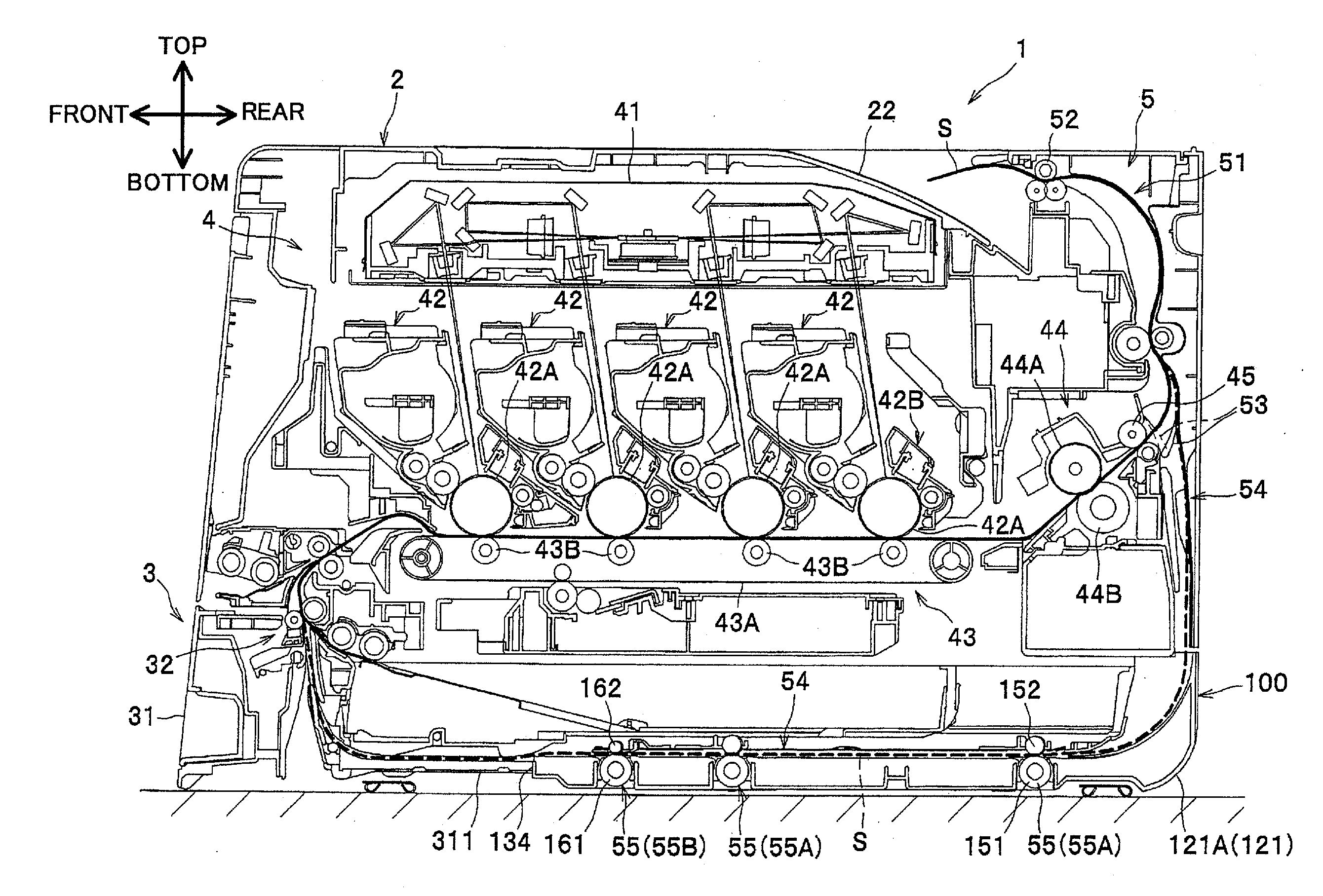
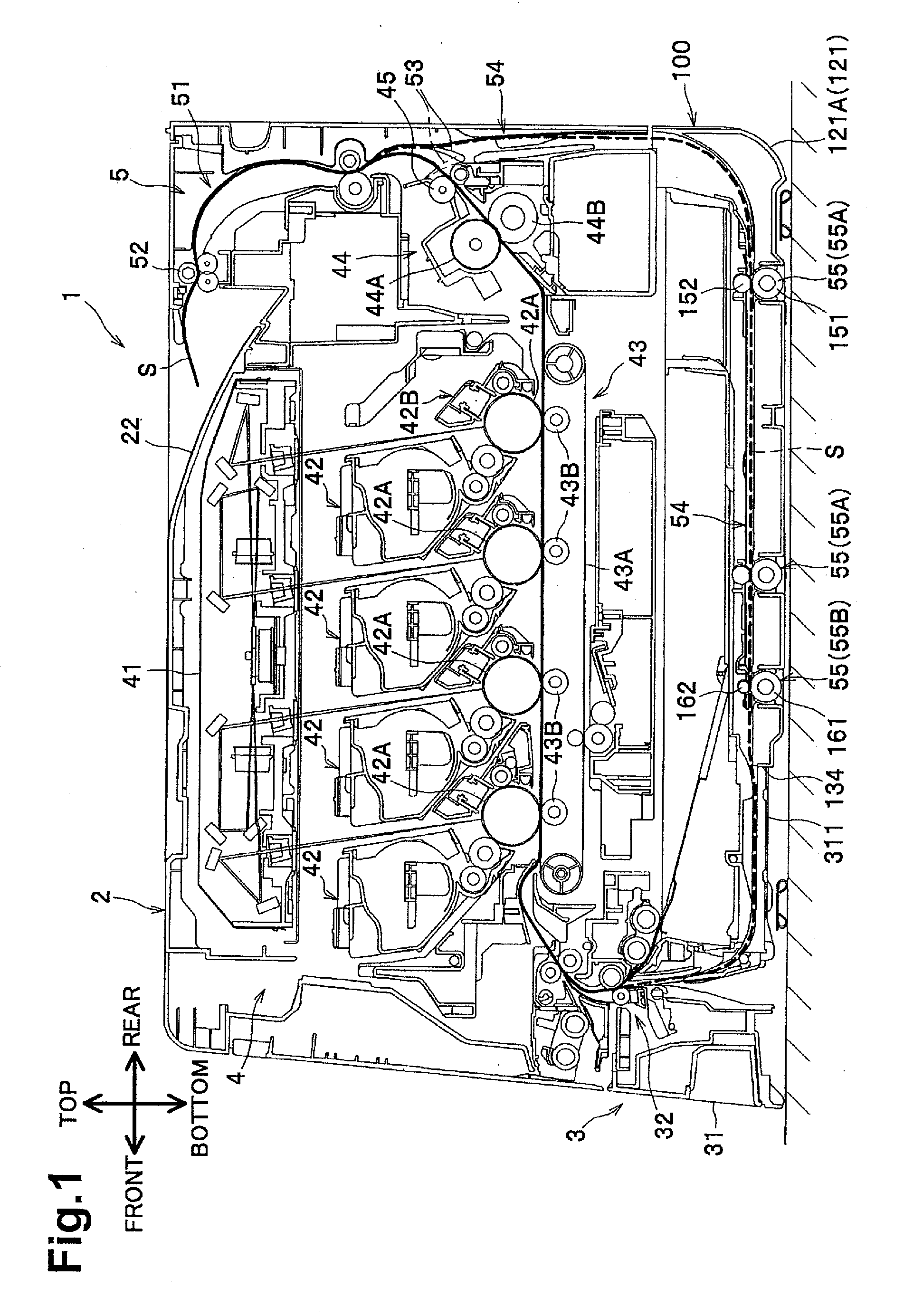
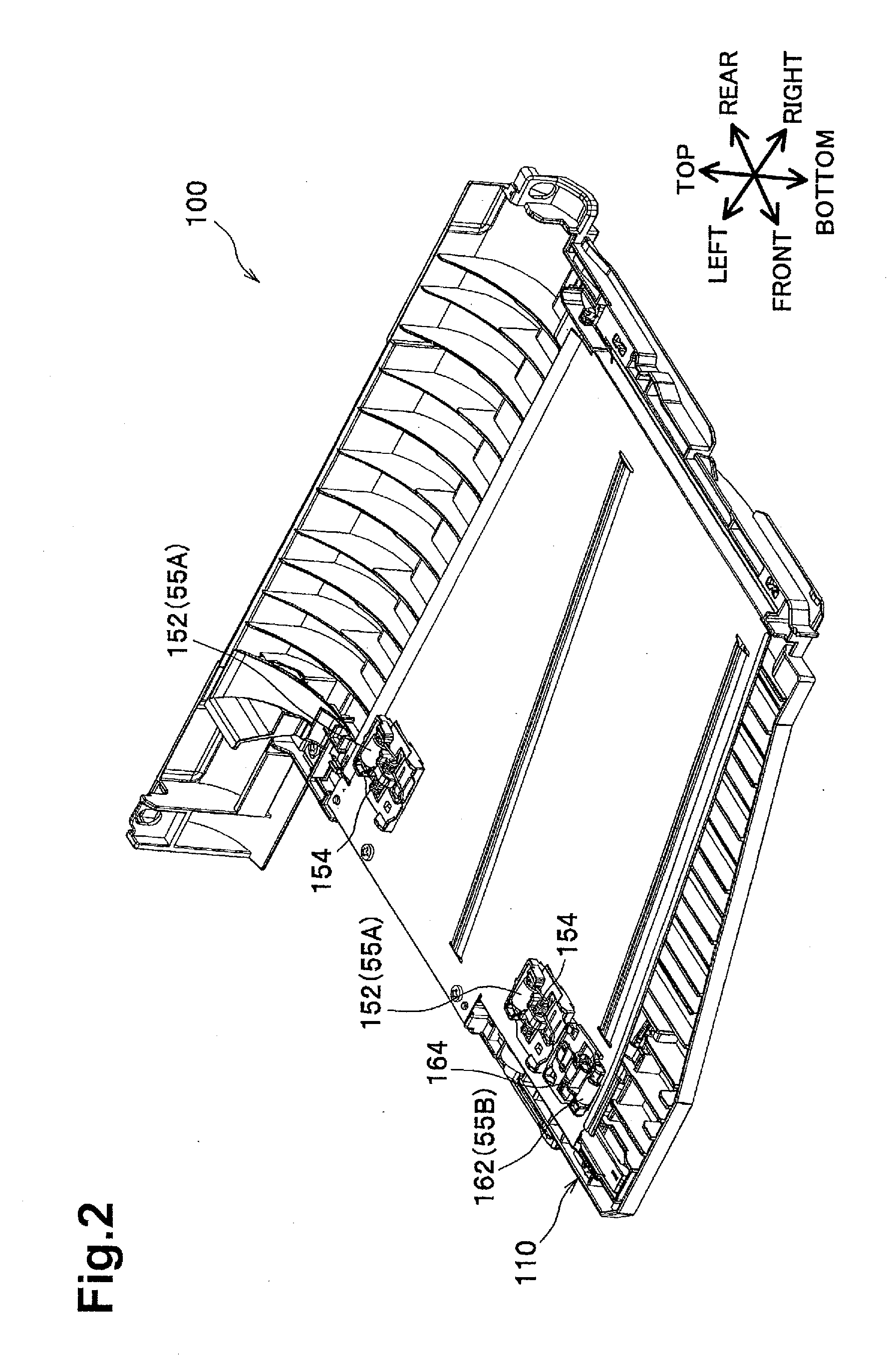
[0020]Hereinafter, an embodiment of the present invention is described in detail with reference to FIG. 1 which depicts a structure of an image forming device, e.g., color printer 1, according to an embodiment of the invention. Color printer 1 may comprise a re-conveying unit 100, which will be described in more detail herein with respect to FIGS. 2-4. In the following descriptions, directions may be defined with reference to a user who is using the color printer 1. Specifically, when oriented as depicted in FIG. 1, the left side of the page may be a “front side,” hereinafter interchangeably referred to as a “near side,” e.g., “nearer” to the user than the opposite side. The right side of the page may be a “rear side,” hereinafter interchangeably referred to as a “back side.” Simil...


PUM

PropertyMeasurementUnit
Angleaaaaaaaaaa
Angleaaaaaaaaaa

Abstract

An image forming device includes a sheet conveyor, an image former that forms an image on a surface of a sheet conveyed by the sheet conveyor, and a re-conveyor that re-conveys the sheet to the image former which forms another image on an opposite surface of the sheet. The re-conveyor includes a guide member including upper and lower conveyance members, a regulation member that regulates a position of the sheet, a conveyer roller set that conveys the sheet therebetween, an urger that urges a pinch roller toward a driving roller, and a roller holder disposed above the upper conveyance member. The upper conveyance member has ends which are secured independently to the lower conveyance member. The roller holder secures the pinch roller overlaps the upper conveyance member in a vertical direction, and secures the pinch roller, such that the pinch roller contacts the sheet through the upper conveyance member.

Description

CROSS-REFERENCE TO RELATED APPLICATION[0001]This application claims priority to Japanese Patent Application No. 2010-243880, filed on Oct. 29, 2010, which is incorporated herein by reference.BACKGROUND OF THE INVENTION[0002]1. Field of the Invention[0003]The invention relates to an image forming device that performs single-sided and double-sided printing.[0004]2. Description of the Related Art[0005]A known image forming device includes a re-conveying unit for returning an inverted paper sheet with an image formed on a first surface thereof to an image forming unit. A known image forming device, e.g., the image forming device described in Japanese Unexamined Patent Application Publication No. 2002-104694, includes conveyor rollers for conveying the paper sheet obliquely toward a one-side regulation member provided at one width direction end of the paper sheet. In a known image forming device, conveyor rollers may have a rubber-made driving roller and a resin-made pinch roller which f...

Claims


Application Information

Patent Timeline
IPC IPC(8): B65H5/26B65H5/06
CPCB65H1/266B65H5/062B65H9/166B65H85/00B65H2301/33312B65H2405/3322B65H2404/54B65H2404/611B65H2404/694B65H2405/111B65H2402/441
Inventor IINO, HIKARUNOBE, HIROSHI
Owner BROTHER KOGYO KK
Why Eureka
Try Eureka