Antenna system and method for optimizing an RF signal

a technology of rf signal and antenna system, applied in diversity/multi-antenna system, transmission monitoring, polarisation/directional diversity, etc., can solve the problems of low signal strength and difficulty in obtaining optimized rf signal, and achieve the effect of switching noise and altering electrical characteristics of rf signal

Active Publication Date: 2012-05-03
AGC AUTOMOTIVE AMERICAS CO A DIV OF AGC FLAT GLASS NORTH AMERICA INC
View PDF10 Cites 10 Cited by
  • Summary
  • Abstract
  • Description
  • Claims
  • Application Information

AI Technical Summary

Benefits of technology

[0010]By utilizing separate evaluation and implementation branch circuits, the system and method optimize the RF signal to the receiver without subjecting the receiver to multiple non-optimized RF signals. Furthermore, switching noise, which occurs when the electrical characteristics of the RF signals are altered, are reduced as the receiver is not subjected to constantly changing RF signals. As such, the receiver typically receives the optimized RF signal in terms of signal strength and signal-to-noise ratio.

Problems solved by technology

However, when either the transmitting or receiving antenna is in motion, such as a receiving antenna disposed on a vehicle or a transmitting antenna on a non-geosynchronous satellite, obtaining the optimized RF signal is more challenging.
Furthermore, switching noise and low signal strength at the receiver may result during the aforementioned process of obtaining the optimized RF signal.

Method used


Image

  • Antenna system and method for optimizing an RF signal
  • Antenna system and method for optimizing an RF signal
  • Antenna system and method for optimizing an RF signal

Examples


first embodiment

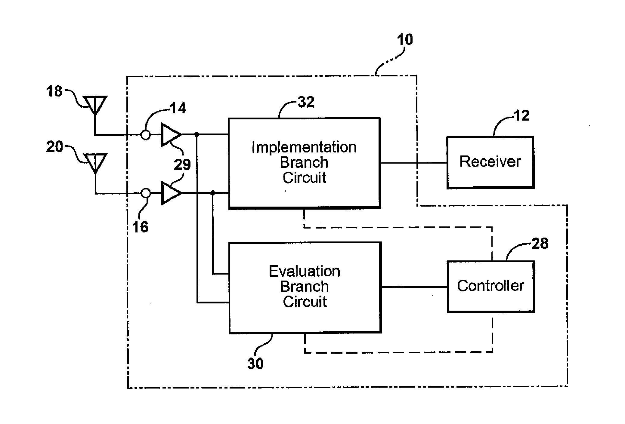
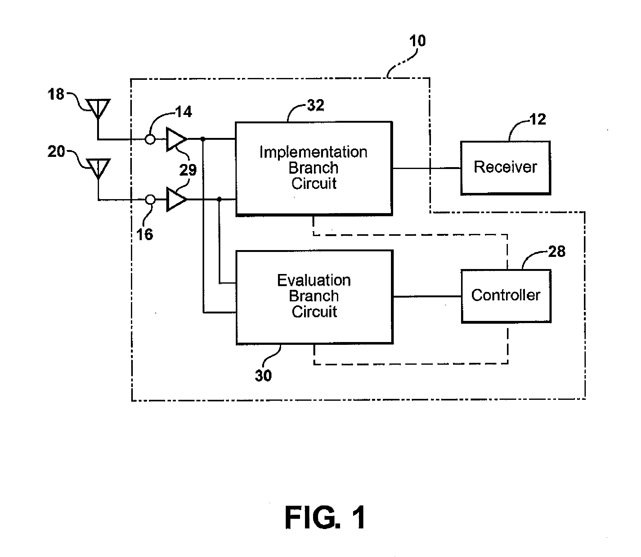
[0027]In the system 10, as shown in FIG. 3, the evaluation branch circuit 30 includes a first evaluation phase shifter 34A electrically connected to an output (not numbered) of the first amplifier 29A. Likewise, the implementation branch circuit 32 includes a first implementation phase shifter 34B also electrically connected to the output of the first amplifier 29A.

second embodiment

[0028]In a second embodiment, as shown in FIG. 4, the evaluation branch circuit 30 includes the first evaluation phase shifter 34A and the first implementation phase shifter 34B electrically connected to the first amplifier 29A. Additionally, a second evaluation phase shifter 34C and a second implementation phase shifter 34D are electrically connected to an output (not numbered) of the second amplifier 29B.

[0029]The circuits 30, 32 may also include the attenuator 36 as one of the at least one signal conditioner 33. Each attenuator 36 attenuates one of the RF signals. That is, the attenuators 36 each reduce the signal strength of the RF signal. Each attenuator 36 is in communication with the controller 28 such that the controller 28 may control the amount or level of attenuation in each attenuator 36. Said another way, the controller 28 manages how much signal strength is reduced by each attenuator 36. By attenuating one or more of the RF signals, the controller 28 optimizes the comb...

third embodiment

[0043]the system also preferably includes a third antenna input 56 and a fourth antenna input 58. The third antenna input 56 is electrically connected to a third antenna group 60 which provides a third RF signal and the fourth antenna input 58 is electrically connected to a fourth antenna group 62 which provides a fourth RF signal. A third amplifier 29C is electrically connected to the third antenna input 56 and a fourth amplifier 29D electrically connected to the fourth antenna input 58. The additional implementation branch 52 is electrically connected to the third and fourth inputs 56, 58.

[0044]The additional implementation branch of the third embodiment is electrically connected to the third and fourth amplifiers 29C, 29D, and thus in communication with the third and fourth antenna groups 56, 58. Specifically, the additional implementation branch 52 includes a fifth phase shifter 34E, a sixth phase shifter 34F, a fifth attenuator 36E, a sixth attenuator 36F, and a third combiner ...


PUM


Abstract

An antenna system and method utilize an evaluation branch circuit and an implementation branch circuit. These circuits are each connected to both a first antenna input and a second antenna input. An output of the evaluation branch circuit is in communication with a controller while an output of the implementation branch circuit is in communication with a receiver. Each branch circuit includes at least one signal conditioner to change an electrical characteristic of RF signals received from antennas via the antenna inputs. The evaluation branch circuit, controlled by the controller, changes the electrical characteristics of the RF signals in a variety of different ways to discover an optimized evaluation RF signal. Once the optimized evaluation RF signal is determined, the implementation branch circuit is controlled, by the controller, to produce an optimized implementation RF signal in accordance with that discovered by the evaluation branch circuit.

Description

CROSS REFERENCE TO RELATED APPLICATIONS[0001]This application claims the benefit of U.S. provisional patent application Nos. 61 / 268,662, 61 / 268,663, 61 / 268,665, 61 / 268,673, 61 / 268,674, and 61 / 268,689, each filed on Jun. 15, 2009 and each of which is hereby incorporated by reference.BACKGROUND OF THE INVENTION[0002]1. Field of the Invention[0003]The subject invention relates to an antenna system and method for optimizing RF signal reception.[0004]2. Description of the Related Art[0005]A receiver performs most effectively when the RF signal it receives is optimized due to a high signal strength and low signal-to-noise ratio. When both the transmitting and receiving antennas are fixed, achieving an optimized RF signal may be accomplished by changing the directionality of one or both of the antennas. However, when either the transmitting or receiving antenna is in motion, such as a receiving antenna disposed on a vehicle or a transmitting antenna on a non-geosynchronous satellite, obtai...

Claims


Application Information

Patent Timeline
Patent Type & Authority Applications(United States)
IPC IPC(8): H04B17/00
CPCH01Q1/1271H01Q1/325H01Q3/2605H01Q3/34H04B17/345H04B7/0848H04B7/0857H04B7/086H04B7/10H04B7/002
Inventor LEE, MINGVILLARROEL, WLADIMIROLEE, KWAN-HOHORIKI, YASUTAKA
Owner AGC AUTOMOTIVE AMERICAS CO A DIV OF AGC FLAT GLASS NORTH AMERICA INC
Why Eureka
Try Eureka