Thermal Management In A Lighting System Using Multiple, Controlled Power Dissipation Circuits

Active Publication Date: 2012-05-10
SIGNIFY HLDG BV
View PDF11 Cites 44 Cited by
  • Summary
  • Abstract
  • Description
  • Claims
  • Application Information

AI Technical Summary

Benefits of technology

[0023]In one embodiment of the present invention, an apparatus includes a controller configured to control a plurality of power dissipation circuits in accordance with a thermal management strategy to dissipate excess energy in a phase cut compatible, dimmable lighting system having one or more light sources selected from a group consisting of at least one light emitting diode and at least one compact fluorescent lamp.
[0024]In another embodiment of the present invention, a method includes controlling a plurality of power dissipation circuits in accordance with a thermal management strategy to dissipate excess e

Problems solved by technology

One of the challenges is developing electronic light source based lamps that are compatible with existing infrastructure.
Another challenge is dissipating heat in electronic light source based lamps.
All switching power converters have some inherent power losses due to, for example, non-ideal component characteristics.
Premature disconnects can cause problems with the lighting system, such as flicker and instability.
However, the potting compound

Method used


Image

  • Thermal Management In A Lighting System Using Multiple, Controlled Power Dissipation Circuits
  • Thermal Management In A Lighting System Using Multiple, Controlled Power Dissipation Circuits
  • Thermal Management In A Lighting System Using Multiple, Controlled Power Dissipation Circuits

Examples


Embodiment Construction

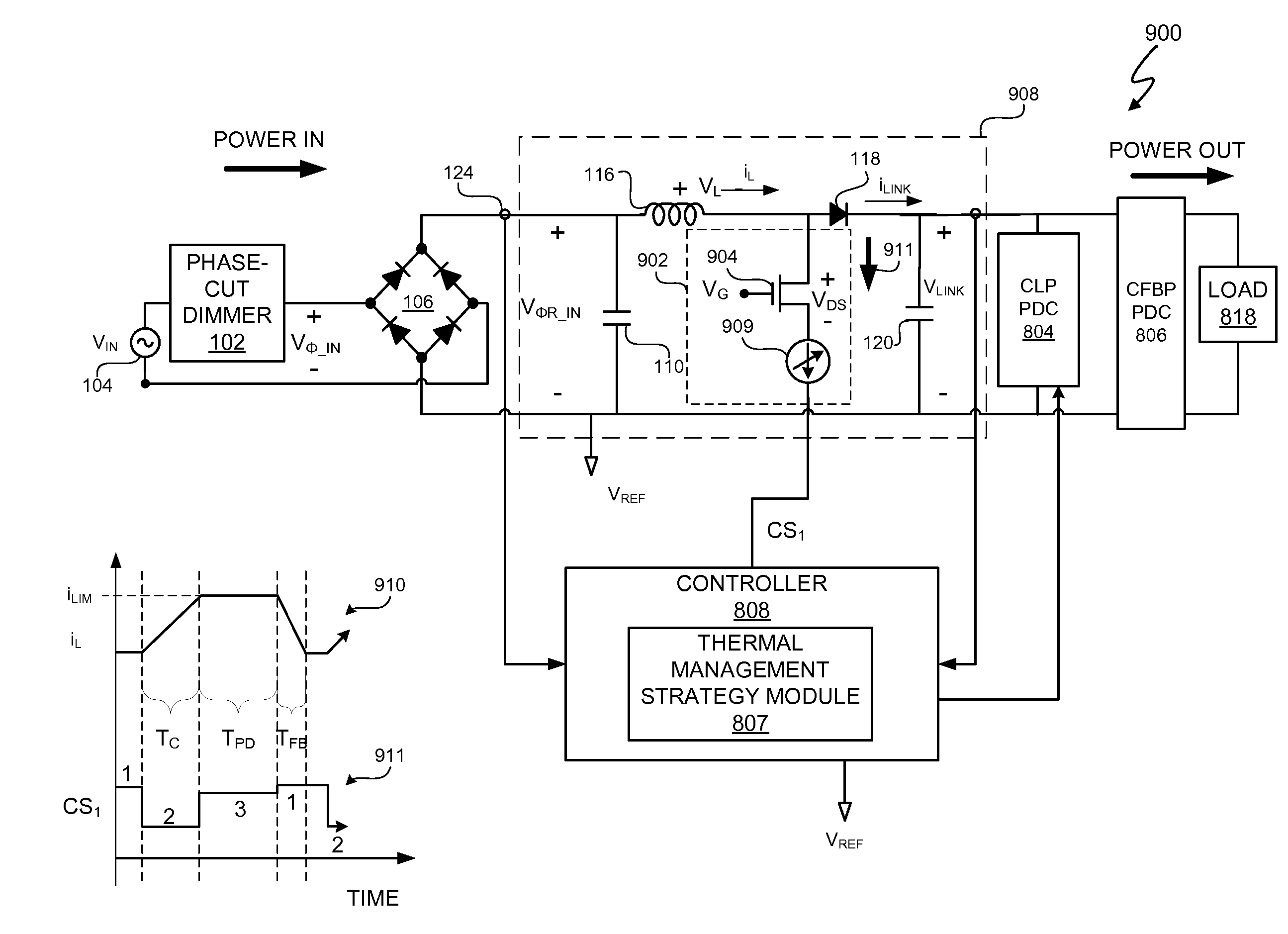
[0047]A lighting system includes a controller that is configured to provide thermal management for the lighting system by distributing excess energy in the lighting system through multiple power dissipation circuits. In at least one embodiment, the lighting system is a phase cut compatible, dimmable lighting system having one or more light sources selected from a group consisting of at least one light emitting diode and at least one compact fluorescent lamp. Thus, in at least some embodiments, the lighting system is an LED-based lighting system, a CFL-based lighting system, and / or a combination LED-based and CFL-based lighting system. In at least one embodiment, the controller is configured to control the plurality of power dissipation circuits in accordance with a thermal management strategy to dissipate the excess energy in the lighting system. In at least one embodiment, the controller is also configured to control a switching power converter of the lighting system. The excess en...


PUM


Abstract

A lighting system includes a controller that is configured to provide thermal management for the lighting system by distributing excess energy in the lighting system through multiple power dissipation circuits. In at least one embodiment, the lighting system is a phase cut compatible, dimmable lighting system having one or more light sources selected from a group consisting of at least one light emitting diode and at least one compact fluorescent lamp. In at least one embodiment, the controller is configured to control the plurality of power dissipation circuits in accordance with a thermal management strategy to dissipate the excess energy in the phase cut compatible, dimmable lighting system. The particular thermal management strategy is a matter of design choice. The power distribution circuits include two of more of: a controlled switch path power dissipation circuit, a controlled link path power dissipation circuit, and a controlled flyback path power dissipation circuit.

Description

CROSS-REFERENCE TO RELATED APPLICATION[0001]This application claims the benefit under 35 U.S.C. §119(e) and 37 C.F.R. §1.78 of U.S. Provisional Application No. 61 / 410,168, filed on Nov. 4, 2010, and is incorporated by reference in its entirety.BACKGROUND OF THE INVENTION[0002]1. Field of the Invention[0003]The present invention relates in general to the field of electronics, and more specifically to a method and system for providing thermal management in a lighting system using multiple, controlled power dissipation circuits.[0004]2. Description of the Related Art[0005]The development and use of energy efficient technologies continues to be a high priority for many entities including many companies and countries. One area of interest is the replacement of incandescent lamps with more energy efficient lamps such as lamps based on electronic light sources. For this description, electronic light sources are light emitting diodes (LEDs) or compact fluorescent lamps (CFLs). As subsequent...

Claims


Application Information

Patent Timeline
IPC IPC(8): H05B37/02H05B44/00
CPCY02B20/19H05B33/0815Y02B20/347Y02B20/346H05B33/0854H05B45/10Y02B20/00Y02B20/30H05B45/3725H05B45/00H05B45/395H05B47/10H05K1/0203H05B45/44H05B45/46
Inventor MELANSON, JOHN L.KING, ERIC J.
Owner SIGNIFY HLDG BV
Why Eureka
Try Eureka