Rotating laser

a laser and rotating technology, applied in the field of rotating lasers, can solve the problem that the bottom surface that is normally provided as the standing surface is not suitable as the standing surface, and achieve the effect of dissipating some of the impact energy and being well protected

Active Publication Date: 2015-12-17
HILTI AG
View PDF11 Cites 5 Cited by
  • Summary
  • Abstract
  • Description
  • Claims
  • Application Information

AI Technical Summary

Benefits of technology

[0027]Especially preferably, the number of shock absorbing elements of the rotating head matches the number of handles. Here, the shapes of the shock absorbing elements of the rotating head and of the upper shock absorbing elements of the handles are harmonized with each other since the protective effect of the shock absorbing elements of the rotating head is particularly effective in conjunction with the upper shock absorbing elements of the handles.
[0028]In a preferred embodiment, the first segments of the handles have an upper shock absorbing element at the upper end facing the rotating head, and the rotating head has several shock absorbing elements, whereby the number of shock absorbing elements of the rotating head matches the number of handles. Rotating lasers are particularly well protected when the handles each have lower and upper shock absorbing elements and when the rotating head likewise has several shock absorbing elements, whereby the number of shock absorbing elements of the rotating head matches the number of handles. Thanks to this configuration of the shock absorbing elements on the handles and on the rotating head, the entire base housing of the rotating laser can be protected.
[0029]The outer surfaces of the grip elements and of the shock absorbing elements that strike an obstacle or land on the ground in case of impact or a fall of the rotating laser especially advantageously enclose an obtuse angle between 90° and 180°. Owing to this configuration of the outer surfaces, the rotating laser can roll on the ground in case of impact or a fall and can thus dissipate some of the impact energy.

Problems solved by technology

Since the lower shock absorbing elements project relative to the bottom surface of the base housing, the bottom surface that is normally provided as the standing surface is not suitable as the standing surface for the rotating laser.

Method used


Image

  • Rotating laser
  • Rotating laser
  • Rotating laser

Examples


Embodiment Construction

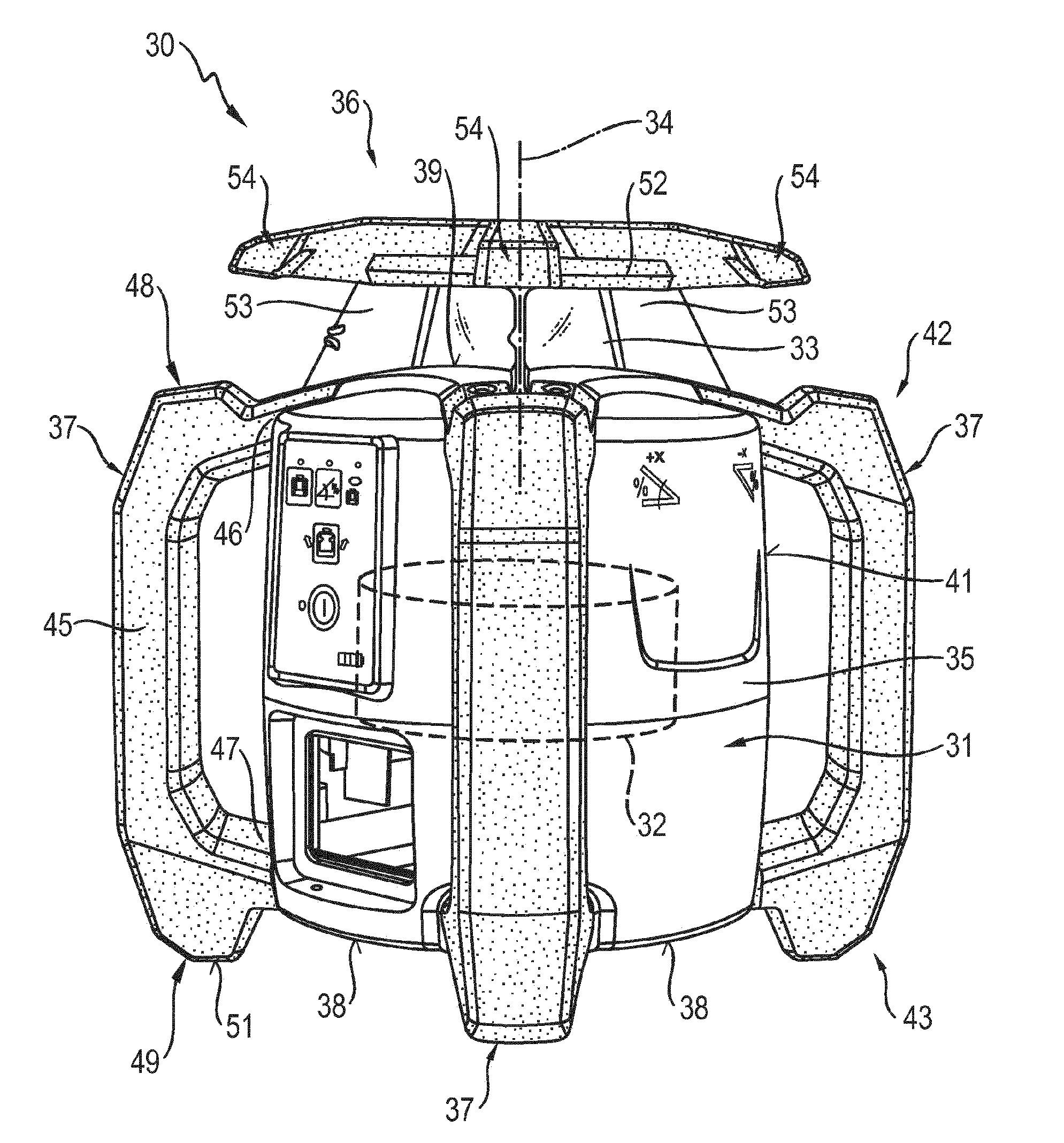
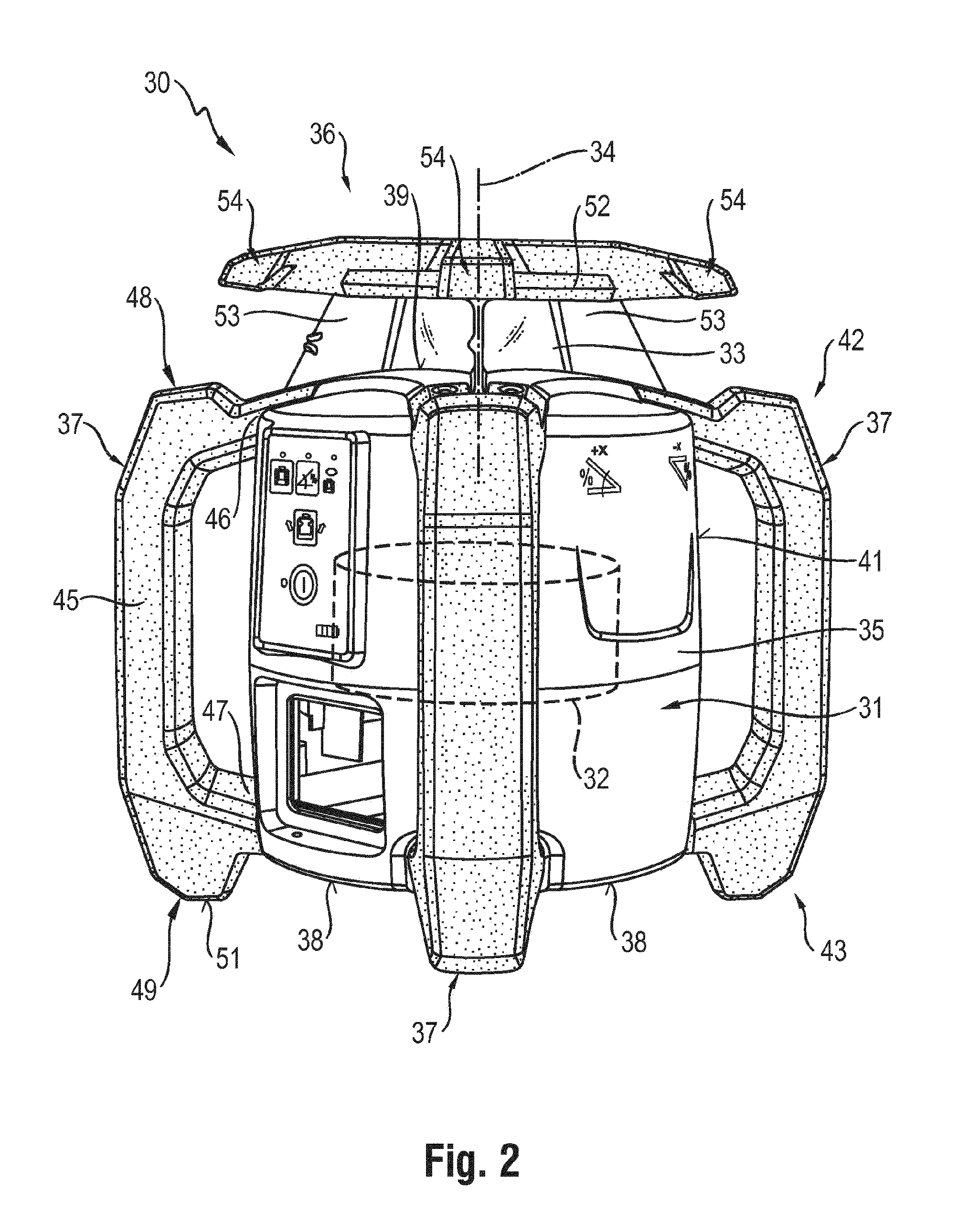
[0037]FIG. 2 shows a measuring device 30 according to the invention that is configured as a rotating laser. The rotating laser 30 comprises a device housing 31 and a measuring unit 32 that is arranged inside the device housing 31 and that is shown schematically in FIG. 2. The measuring unit 32 generates a laser beam in a radiation source, and this laser beam strikes a rotating optical deflector 33. The laser beam exits from the radiation source in an axial direction and it is deflected by 90° in a radial direction by means of the optical deflector 33. The optical deflector 33 rotates around the axis of rotation 34 that runs parallel to the axial direction of the emitted laser beam.

[0038]The device housing 31 of the rotating laser 30 comprises a base housing 35, a rotating head 36 and several handles 37. FIG. 2 shows a device housing 31 with four identically configured handles 37 that are arranged uniformly around the base housing 35. As an alternative, the device housing 31 can have...


PUM


Abstract

A rotating laser (30), including a device housing (31) having a base housing (35), a rotating head (36) and three or more handles (37), whereby the base housing (35) includes a bottom surface (38), a top surface (39) opposite from the bottom surface (38) and a side surface (41) that connects the bottom and top surfaces (38, 39), and a measuring unit (32) that is arranged at least partially inside the device housing (31), whereby the handles (37) have a first segment with a grip element (45), and a lower shock absorbing element (49) at the lower end (43) of the handles (37) facing away from the rotating head (36), and the lower shock absorbing elements (49) project relative to the bottom surface (38) in an axial direction parallel to the axis of rotation (34).

Description

[0001]The present invention relates to a rotating laser comprising a device housing and a measuring unit.BACKGROUND[0002]Known measuring devices comprise a housing and a measuring unit arranged inside the device housing. FIG. 1 shows a prior-art measuring device 10 configured as a rotating laser, consisting of a device housing 11 and of a measuring unit 12 that is arranged in the device housing 1 and that is shown schematically in FIG. 1. The device housing 11 of the rotating laser 10 has a base housing 13, a rotating head 14 and several handles 15. The base housing 13 is configured to be essentially cylindrical and it comprises a bottom surface 16, a top surface 17 opposite from the bottom surface 16 and a side surface 8 that connects the bottom and top surfaces 16, 17. The rotating head 14 comprises a cover element 21 that is connected to the top surface 17 of the base housing 13 via several crosswise webs 22 that are connected to each other. The handles 15 comprise a grip element...

Claims


Application Information

Patent Timeline
Patent Type & Authority Applications(United States)
IPC IPC(8): G01D11/24
CPCG01D11/245G01C15/04G01D11/24
Inventor LUKIC, SASHALAMPERT, PATRICKGASNAKIS, STELIOSFELSBERGER, FRANZ
Owner HILTI AG
Why Eureka
Try Eureka