Linear actuator

Active Publication Date: 2012-05-17
SMC CORP
View PDF6 Cites 3 Cited by
  • Summary
  • Abstract
  • Description
  • Claims
  • Application Information

AI Technical Summary

Benefits of technology

[0006]For preventing chattering / backlash between the guide rail (first member) and the movable element (second member), pre-compression is applied to the rolling bodies by making the diameter of the rolling bodies greater, for example, on the order of a few μm, than the contact diameter of the rolling bodies in the rolling grooves (i.e., the diameter of the rolling bodies when the rolling bodies are accommodated in the rolling grooves). For making the contact diameter of the rolling bodies in the rolling grooves smaller than the diameter of the rolling bodies, various techniques are used, such as (1) adjusting the shape of the rolling grooves of the guide rail and the movable element, (2) altering the combination of the guide rail and the movable element that is used, and (3) using rolling bodies that initially are larger in diameter than the aforementioned contact diameter.
[0009]The present invention has been made taking into consideration the problems of the conventional techniques discussed above, and has an object of providing a linear actuator in which, by means of a simple structure, chattering / backlash between a first member and a second member can be prevented, differential slippage of the rolling bodies can be suppressed, and miniaturization of the linear actuator can be facilitated.
[0018]According to the present invention, the first rolling grooves and the second rolling grooves, which rollably support the rolling bodies, are provided on the projections on the opposite end sides of the first member and on the second member, and the first rolling grooves and the second rolling grooves apply a pressure on the rolling bodies, caused by a magnetic attractive force of the magnet. Therefore, chattering / backlash between the first member and the second member can be prevented, together with suppressing differential slippage of the rolling bodies and achieving a reduction in scale of the linear actuator. Compared to a gothic arch structure or a circular structure, a high level of precision in machining accuracy and assembly accuracy of the rolling bodies, and the first and second rolling grooves is not required, and thus, the process steps for machining and assembling the linear actuator can be lessened.

Problems solved by technology

However, using the above techniques, problems tend to occur in that, with the first technique (1), a high level of machining accuracy on the order of a few μm is required, with the second technique (2), a high level of assembly accuracy on the order of a few μm is required, and with the third technique (3), appropriate selection of the rolling bodies is difficult to perform.
Further, in the case of supporting the rolling bodies in rolling grooves constructed in the form of two rows of gothic arches, it is necessary for the rolling grooves to be machined with high precision, and furthermore, a defect occurs in that differential slippage of the rolling bodies causes frictional forces to increase.
Further, in the case that rolling grooves having a circular structure are used, in which the supporting directions thereof are arranged at mutual right angles to support loads in two directions, although an advantage results in that differential slippage can be made smaller than with the aforementioned gothic arch structure, the structure becomes complex overall because four rows of rolling grooves are required, and miniaturization (reduction in scale) of the linear actuator is made more difficult.

Method used


Image

  • Linear actuator
  • Linear actuator
  • Linear actuator

Examples


first embodiment

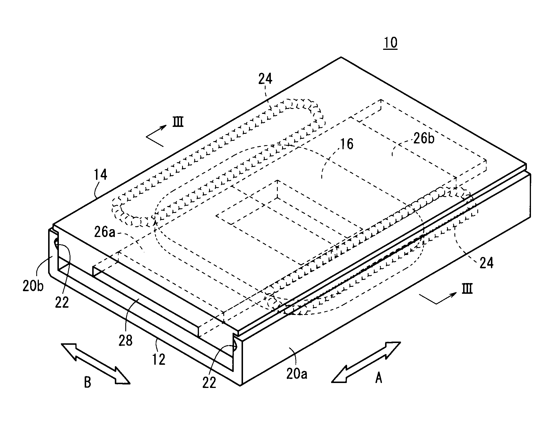
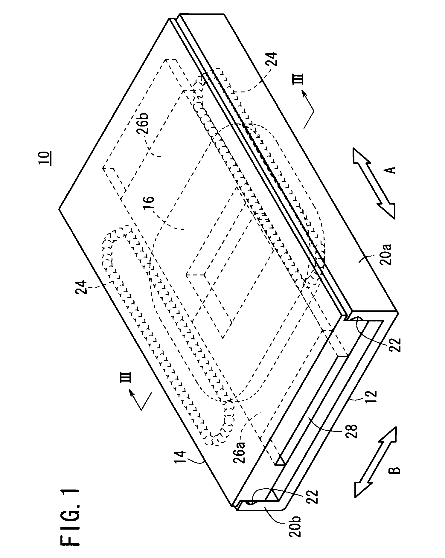
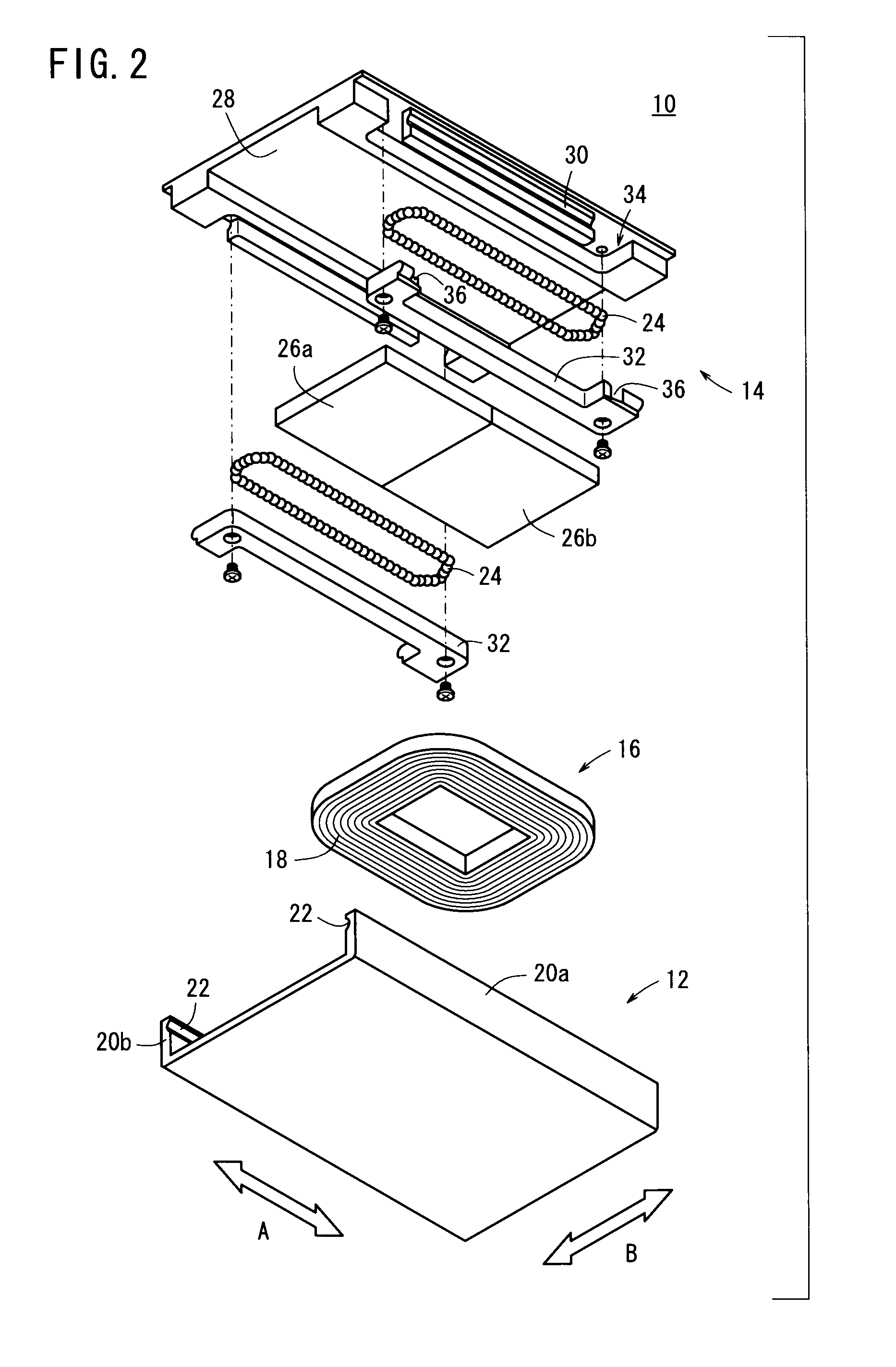
[0063]FIG. 1 is a perspective view showing a linear actuator 10 according to a first embodiment of the present invention, FIG. 2 is an exploded perspective view of the linear actuator 10, and FIG. 3 is a cross sectional view as seen in the direction of the arrows and taken along line of FIG. 1.

[0064]The linear actuator 10 according to the first embodiment is equipped with a guide rail (first member) 12 and a slide table (second member) 14, which is arranged in confronting relation to the guide rail 12. The guide rail 12 is U-shaped in cross section, and a coil 16, which faces toward the slide table 14, is disposed on the guide rail 12. The coil 16 is a doughnut-shaped or air core coil, in which an insulative film covered conductive wire is wound, and the coil is further formed by molding with an insulated body 18 made of resin. The coil 16 is disposed substantially centrally on an upper surface of the guide rail 12.

[0065]On opposite sides in the lateral direction (directions of the ...

second embodiment

[0083]FIG. 6 is a perspective view of a linear actuator 100 according to a second embodiment, FIG. 7 is an exploded perspective view as seen from above the linear actuator 100, FIG. 8 is an exploded perspective view as seen from below the linear actuator 100, FIG. 9 is a cross sectional view as seen in the direction of the arrows and taken along line IX-IX of FIG. 6, and FIG. 10 is a cross sectional view as seen in the direction of the arrows and taken along line X-X of FIG. 6.

[0084]The linear actuator 100 according to the second embodiment includes a cylinder main body 102, a slide table (first member) 104 disposed on an upper portion of the cylinder main body 102 and which moves reciprocally and linearly along the longitudinal direction (in directions of the arrow C), a guide mechanism (second member) 106 interposed between the cylinder main body 102 and the slide table 104, which guides the slide table 104 along the longitudinal direction (in directions of the arrow C), and a sto...


PUM


Abstract

A linear actuator displaces a relative position between a guide rail and a slide table, which is arranged in confronting relation to the guide rail. Projections are formed on opposite end sides of the guide rail, the projections extending along a direction of displacement and projecting toward the slide table. The slide table is disposed between the projections on the opposite end sides of the guide rail, with rigid balls being interposed therebetween. Guide grooves and guide grooves, which rollably support the balls, are provided on the projections on the opposite end sides of the guide rail and on the slide table. The guide grooves and the guide grooves apply, on the balls, a pressure caused by a magnetic attractive force of permanent magnets.

Description

CROSS-REFERENCE TO RELATED APPLICATION[0001]This application is based upon and claims the benefit of priority from Japanese Patent Application No. 2010-254552 filed on Nov. 15, 2010, of which the contents are incorporated herein by reference.BACKGROUND OF THE INVENTION[0002]1. Field of the Invention[0003]The present invention relates to a linear actuator for displacing a relative position between a first member and a second member, which is arranged in confronting relation to the first member, while preventing chattering / backlash from occurring between the first member and the second member.[0004]b 2. Description of the Related Art[0005]A linear actuator is known in which a relative position between a guide rail and a slide table, which is disposed to confront the guide rail, is displaced. As disclosed in Japanese Laid-Open Patent Publication No. 2010-161926, for enabling displacement of the guide rail and the slide table, for example, spherical shaped rolling bodies are interposed ...

Claims


Application Information

Patent Timeline
IPC IPC(8): H02K41/035H02K41/02
CPCF16C29/007F16C29/064F16C29/12H02K41/031H02K7/08
Inventor YAJIMA, HISASHIHOSAKA, TATSUYASATO, TOSHIO
Owner SMC CORP
Why Eureka
Try Eureka