Determining user intent from position and orientation information

a technology of user intent and position and orientation information, applied in the field of consumer electronics, can solve the problems of requiring dedicated buttons and a large number of remote controls to be used, and achieve the effect of reducing the number of remote controls that were required to be used and reducing the number of users

Inactive Publication Date: 2012-05-24
SAMSUNG ELECTRONICS CO LTD
View PDF113 Cites 64 Cited by
  • Summary
  • Abstract
  • Description
  • Claims
  • Application Information

AI Technical Summary

Benefits of technology

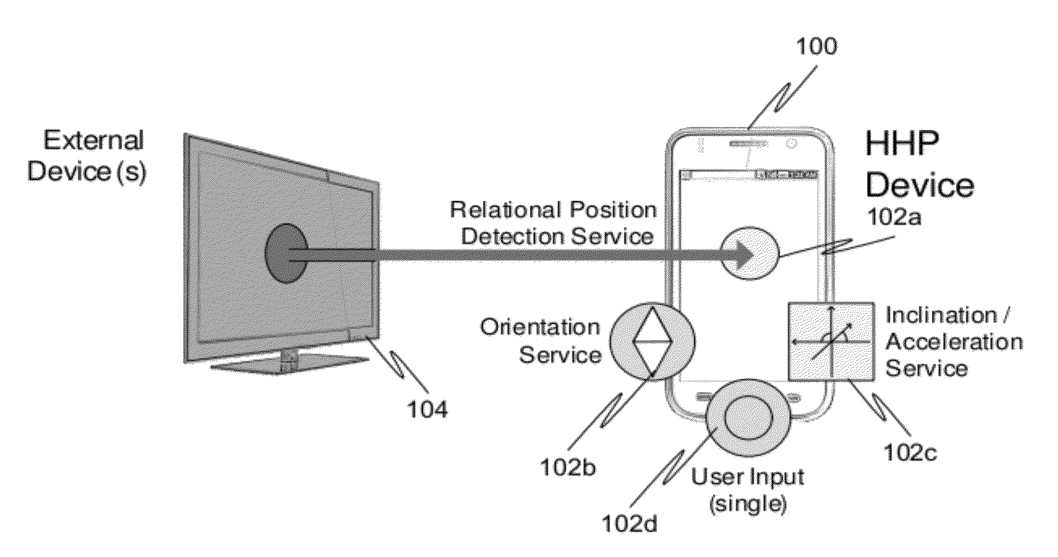
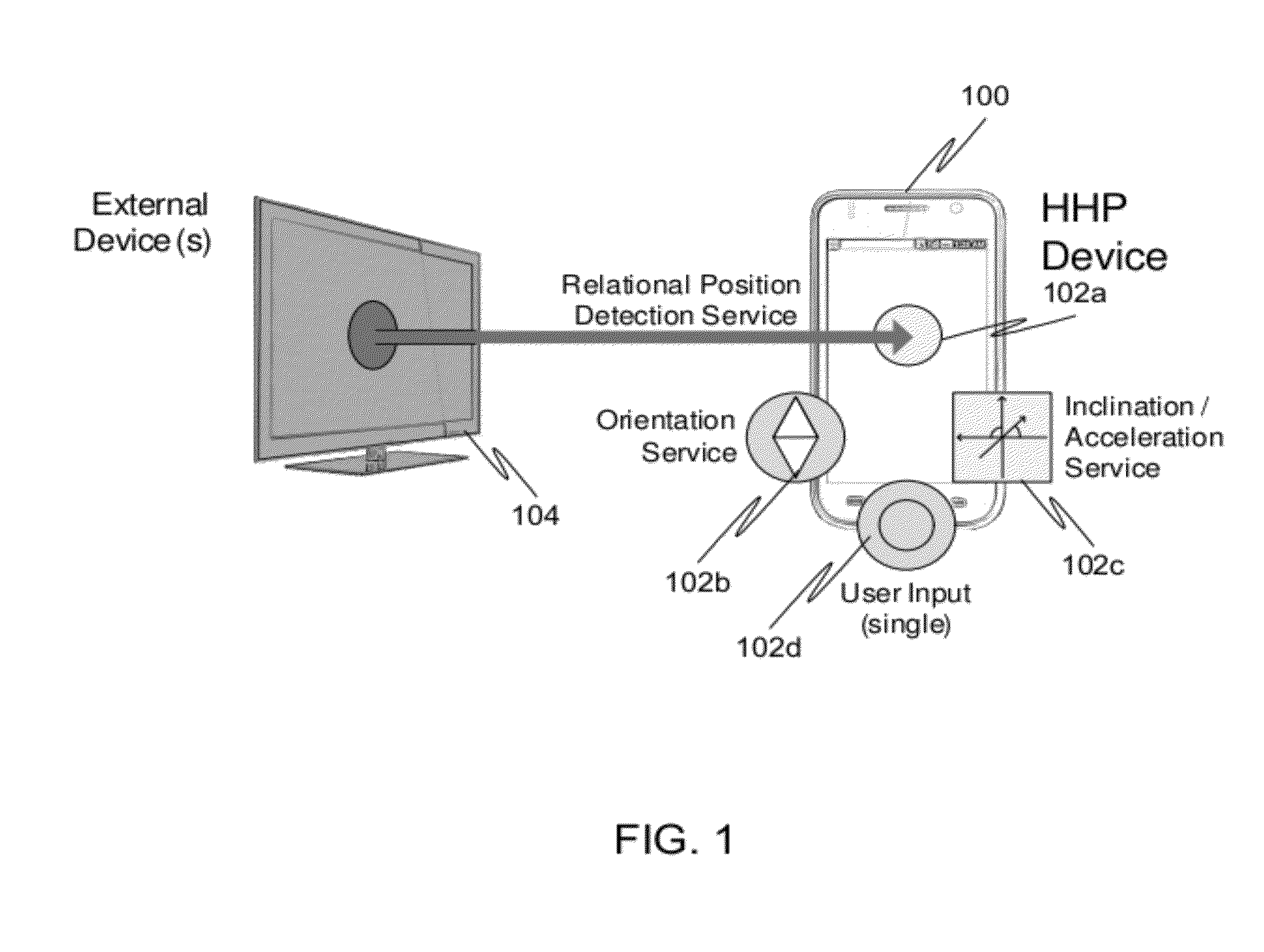
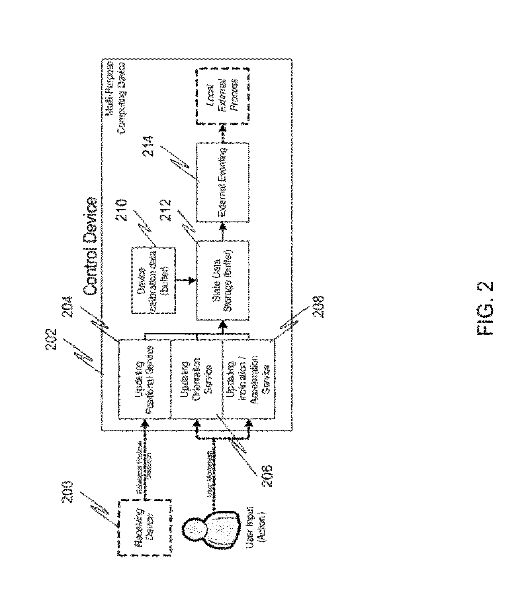
[0009]In a first embodiment of the present invention, a method for controlling a receiving device, the method comprising: detecting a position of a control device operated by a user; detecting horizontal orientation or vertical inclination of the control device; based on the position and the horizontal orientation or vertical inclination of the control device, determining that the control device is pointed at the receiving device as opposed to another receiving device in the vicinity; and causing the control device to control the receiving device at which it is pointed based on the determination that the control device is pointed at the receiving device.
[0010]In a second embodiment of the present invention, a control device is provided, comprising: a position sensor designed to track position of the control device with respect to two or more receiving devices in proximity of the control device; an orientation sensor designed to track horizontal orientation of the control device; and an eventing module designed to determine at which of the two or more receiving devices the control device is pointing, based upon the tracked position and horizontal orientation, and to generate an event to the corresponding receiving device based upon that det

Problems solved by technology

As the number of these devices increased, however, the number of remote controls that were required to be used grew unwieldy.
The drawback to this approach, however, is that it req

Method used


Image

  • Determining user intent from position and orientation information
  • Determining user intent from position and orientation information
  • Determining user intent from position and orientation information

Examples


Embodiment Construction

[0026]Reference will now be made in detail to specific embodiments of the invention including the best modes contemplated by the inventors for carrying out the invention. Examples of these specific embodiments are illustrated in the accompanying drawings. While the invention is described in conjunction with these specific embodiments, it will be understood that it is not intended to limit the invention to the described embodiments. On the contrary, it is intended to cover alternatives, modifications, and equivalents as may be included within the spirit and scope of the invention as defined by the appended claims. In the following description, specific details are set forth in order to provide a thorough understanding of the present invention. The present invention may be practiced without some or all of these specific details. In addition, well known features may not have been described in detail to avoid unnecessarily obscuring the invention.

[0027]In accordance with the present inv...


PUM


Abstract

In a first embodiment of the present invention, a method for controlling a receiving device, the method comprising: detecting a position of a control device operated by a user; detecting horizontal orientation or vertical inclination of the control device; based on the position and the horizontal orientation or vertical inclination of the control device, determining that the control device is pointed at the receiving device as opposed to another receiving device in the vicinity; and causing the control device to control the receiving device at which it is pointed based on the determination that the control device is pointed at the receiving device.

Description

CROSS REFERENCE TO RELATED APPLICATIONS[0001]This application claims the benefit of priority under 35 U.S.C. 119(e) to U.S. Provisional Patent Application No.: 61 / 416,979, filed Nov. 24, 2010, which is incorporated herein by reference for all purposes.BACKGROUND OF THE INVENTION[0002]1. Field of the Invention[0003]The present invention relates to consumer electronics. More specifically the present invention relates to the determining of user intent from position and orientation information.[0004]2. Description of the Related Art[0005]The explosion of network-enabled consumer devices in recent years has given rise to a relatively new phenomenon in that is becoming more and more common for individual rooms in a house (such as a living room) to contain a number of different network-enabled devices. For example, it is not uncommon for a living room to contain a network-enabled television, network-enabled DVD or Blu-ray player, network-enabled digital picture frames, a network-enabled st...

Claims


Application Information

Patent Timeline
IPC IPC(8): H04L17/02G01S15/08G01C3/08G05B19/00
CPCG06F1/1694G06F3/0346G06F3/0383H04B1/202H04N21/42204H04M2250/12H04N21/4126H04N21/42202H04M1/72533H04M1/72415H04N21/41265
Inventor GICKLHORN, DANIEL P.TRAN, DANGLOVELACE, MICHAEL R.SHELANSKY, ANDREW R.
Owner SAMSUNG ELECTRONICS CO LTD
Why Eureka
Try Eureka