Disc brake for a tape measure

Inactive Publication Date: 2012-05-31
NIELSON ROB
View PDF11 Cites 7 Cited by
  • Summary
  • Abstract
  • Description
  • Claims
  • Application Information

AI Technical Summary

Benefits of technology

[0015]The disc brake mechanism may prevent the measuring tape from freewheeli

Problems solved by technology

However, conventional locking mechanisms do not control the rate at which the measuring tape retracts into the housing when the locking

Method used


Image

  • Disc brake for a tape measure
  • Disc brake for a tape measure
  • Disc brake for a tape measure

Examples


Embodiment Construction

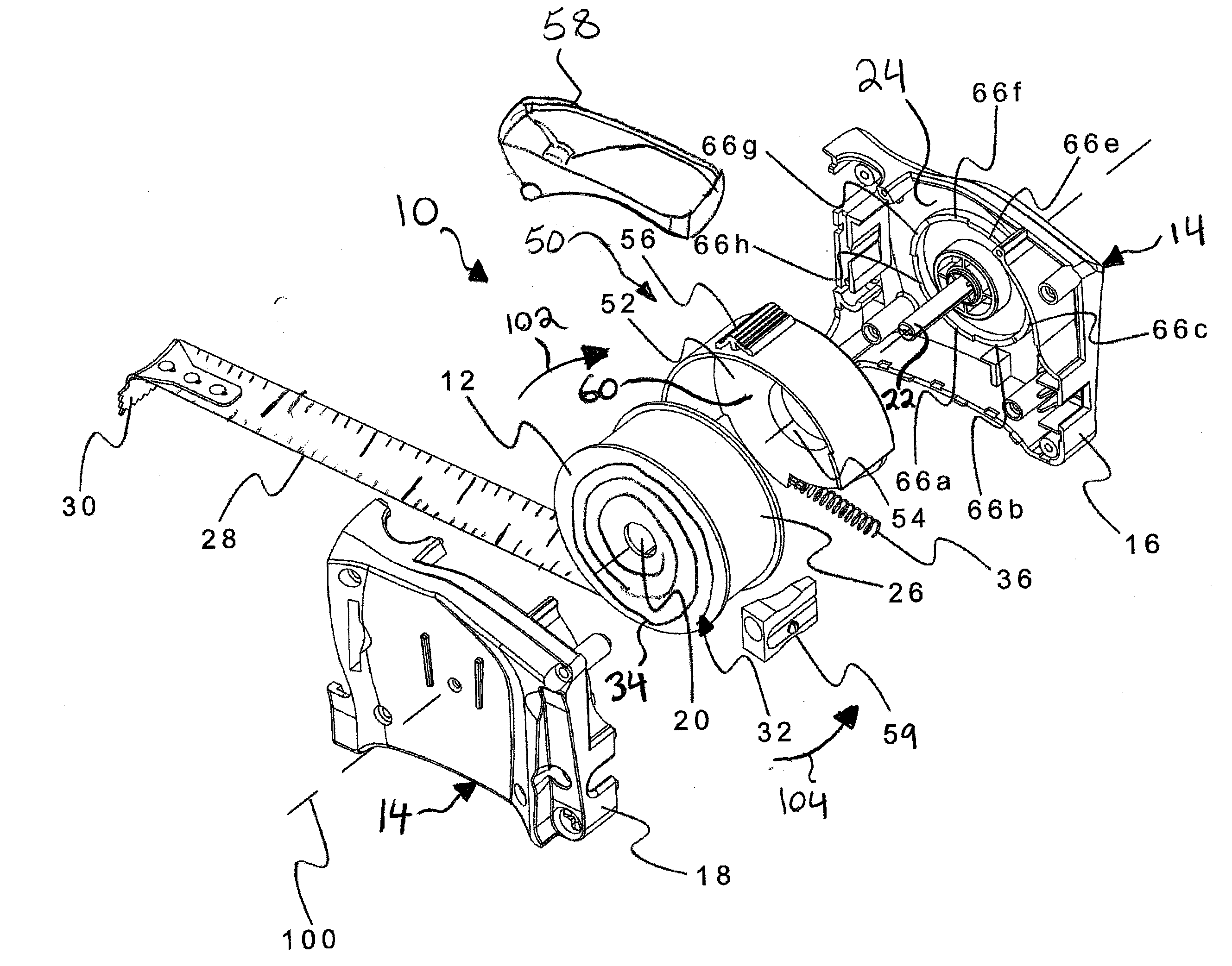
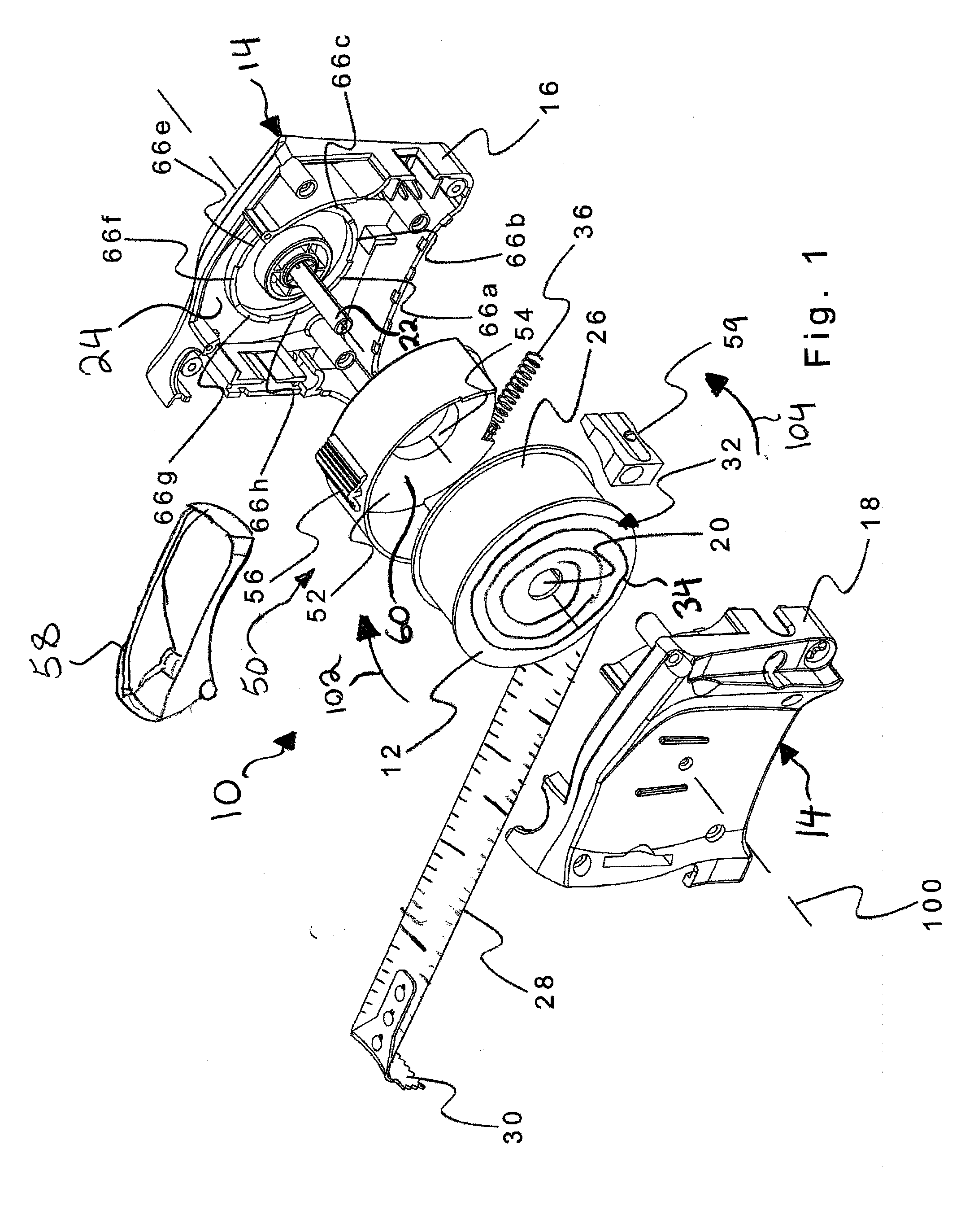
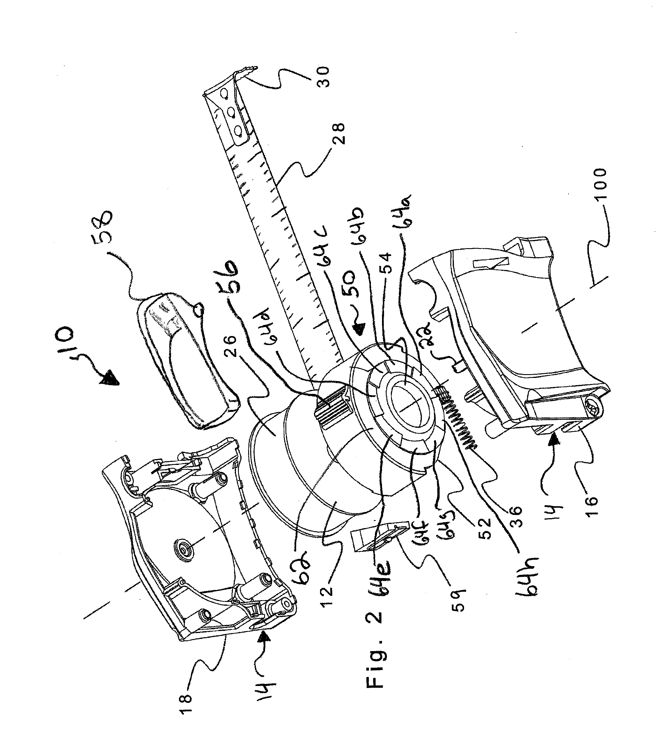
[0025]Referring to the drawings and first to FIGS. 1 and 2, these show exploded views of an improved tape measure 10. The tape measure 10 includes a tape reel 12 which is cylindrical in this example and disposed within a housing 14. In this example, the housing 14 includes two housing halves 16 and 18. The tape reel 12 has an opening 20 extending through a center thereof. The opening 20 allows the tape reel 12 to be rotatably mounted on a shaft 22 that extends from an inner wall 24 of a first one of the housing halves 16. The tape reel 12 is also provided with a spring mechanism 32. In this example, the spring mechanism 32 includes a coiled flat spring 34. A measuring tape 26 is attached to and coiled about a hub (not shown) of the tape reel 12. The measuring tape 26 is provided with measuring indicia 28 displayed thereon and a hook 30 at a free end thereof.

[0026]The measuring tape 26 is movable between an extended position and a retracted position. In the extended position the meas...


PUM


Abstract

A tape measure comprises a housing having a tape reel rotatably mounted therein. A measuring tape is at least partially coiled about the tape reel. The measuring tape is movable between an extended position and a retracted position. In the extended position at least a portion of the measuring tape extends outwardly of the housing. In the retracted position the measuring tape is substantially coiled about the tape reel and disposed within the housing. A spring mechanism biases the tape reel to rotate so as move the measuring tape from the extended position to the retracted position. A disc brake mechanism applies a frictional force to the tape reel to control rotation of the tape reel.

Description

CROSS-REFERENCE TO RELATED APPLICATION[0001]This application claims the benefit of provisional application 61 / 221,493 filed in the United States Patent and Trademark Office on Jun. 29, 2010, the disclosure of which is incorporated herein by reference and priority to which is claimed.BACKGROUND OF THE INVENTION[0002]1. Field of the Invention[0003]The present invention relates to a tape measure and, in particular, to a tape measure provided with a disc brake mechanism.[0004]2. Description of the Related Art[0005]Tape measures generally include a measuring tape coiled about a tape reel disposed within a housing. A hook mounted on a free end of the measuring tape extends through a slot in the housing. This allows a user to extend the measuring tape outwardly of the housing in order to take a measurement using measuring indicia displayed on the measuring tape. In spring loaded tape measures, a spring mechanism biases the tape reel to retract the measuring tape into the housing to facilit...

Claims


Application Information

Patent Timeline
IPC IPC(8): G01B3/10
CPCF16D2121/14G01B3/1005F16D2125/38
Inventor HUNSBERGER, MATTHEWNIELSON, ROB
Owner NIELSON ROB
Why Eureka
Try Eureka