

Suspension Including Coil Spring and Ambient Air Cushion
- Summary
- Abstract
- Description
- Claims
- Application Information
AI Technical Summary
Benefits of technology
Problems solved by technology
Method used
Image

Examples
first embodiment
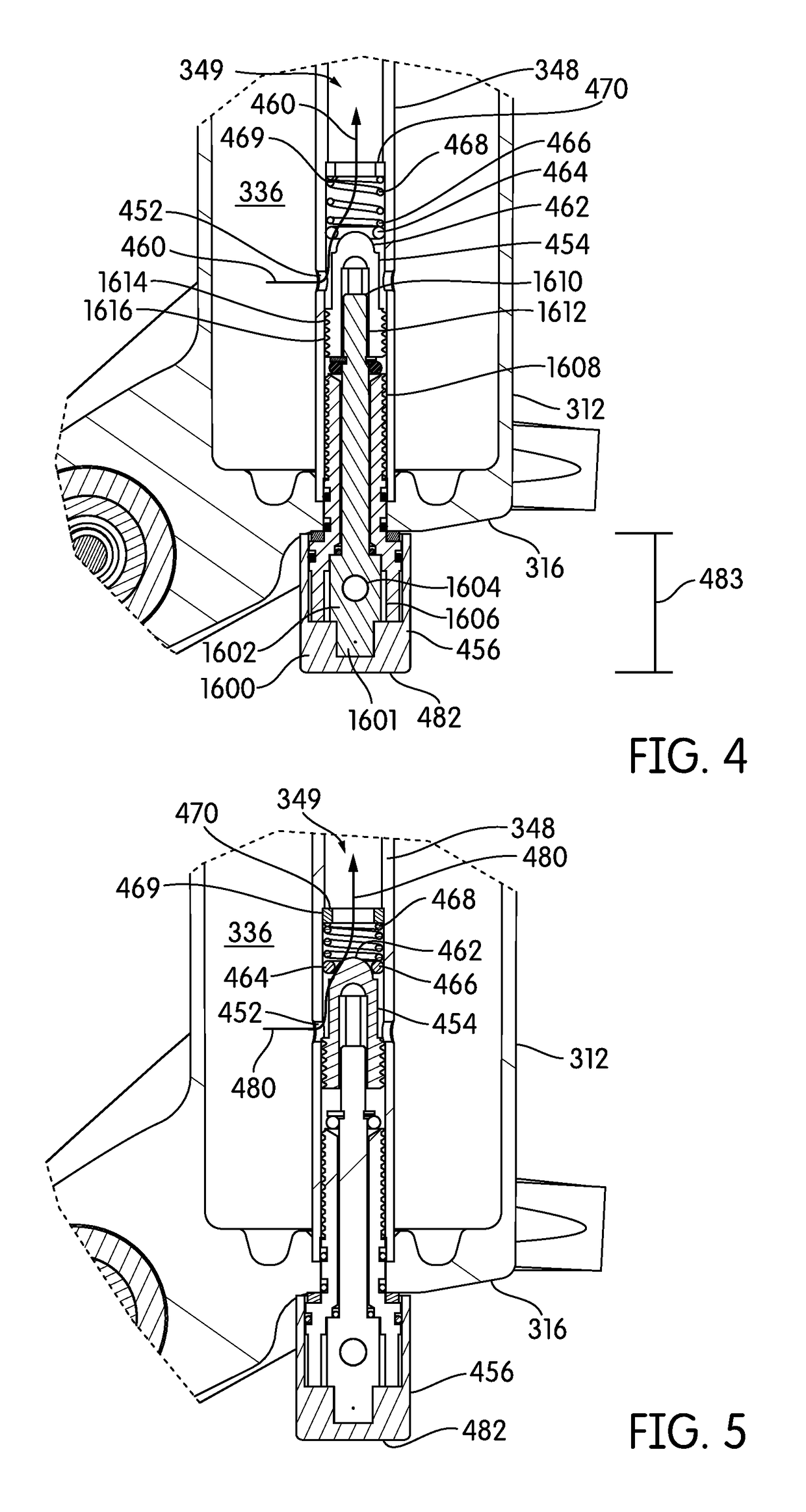
[0054]FIGS. 4 and 5 show a damping system 350. The damping system may include the hollow rod 348. At least one or a series of orifices 452 may be defined in the hollow rod 348. The orifices may permit gas to flow between the first chamber 336 and an interior cavity 349 within the hollow rod 348. In many embodiments, the hollow rod 348 may be open at its free end 347. Therefore, in many embodiments, gas may be permitted to flow from the compression chamber 336, through the hollow rod 348 and into the second chamber 338. The manner or rate in which gas is permitted to flow may be defined by the position of an adjustable damping blocker 454.
[0055]The adjustable blocker 454 may be positioned within the interior cavity 349 of the hollow rod 348. One end of the adjustable blocker 454 may be attached to an adjuster 456. The adjuster 456 may extend outside the closed end 316 of the first tube 312, and may include a knob, dial, or other structure that may allow a rider or any other person to...
second embodiment
[0061]FIGS. 6 and 7 show a damping system 350. The damping system may include the hollow rod 348. At least one or a series of orifices 652 may be defined in the hollow rod 348. The orifices may permit gas to flow between the first chamber 336 and the interior cavity 349 within the hollow rod 348. In many embodiments, the hollow rod 348 may be open at its free end 347. Therefore, in many embodiments, gas may be permitted to flow from the compression chamber 336, through the interior cavity 349 of the hollow rod 348 and into the second chamber 338. The manner and rate in which gas is permitted to flow may be defined by the position of the damping blocker 654.
[0062]The damping blocker 654 may be positioned within the interior cavity 349 of the hollow rod 348. One end of the damping blocker 654 may be attached to an adjuster 656. The free end 682 of the adjuster 656 may extend outside the first tube 312, and may include a knob, dial, or other structure that may allow a rider or any othe...
third embodiment
[0067]FIGS. 8 and 9 show a damping system 350. The damping system may include the hollow rod 348. At least one or a series of orifices 852 may be defined in the hollow rod 348. The orifices may permit gas to flow between the first chamber 336 and the interior cavity 349 within the hollow rod 348. In many embodiments, the hollow rod 348 may be open at its free end 347. Therefore, in many embodiments, gas may be permitted to flow from the compression chamber 336, through the hollow rod 348 and into the second chamber 338. The manner and rate in which gas is permitted to flow may be defined by the position of the damping blocker 854.
[0068]The damping blocker 854 may be positioned within the interior cavity 349 of the hollow rod 348. One end of the damping blocker 854 may be attached to an adjuster 856. The free end 882 of the adjuster 856 may extend outside the first tube 312, and may include a knob, dial, or other structure that may allow a rider or any other person to adjust the posi...
PUM
 Abstract
Description
Claims
Application Information