Image encoding device, electronic camera and recording medium for image encoding program

Active Publication Date: 2005-04-05
NIKON CORP
9 Cites 5 Cited by

AI-Extracted Technical Summary

Problems solved by technology

This leads to problems such as a noticeable drop in the image quality ...

Method used

Additionally, a case may also be envisioned in which the quantity of image information in the image as a whole is small to begin with, so that the bit allocation rate of the non-selected region cannot be effectively lowered regardless of how far the area of the selected region is expanded. In such a case, unnecessary expansion of the area of the selected region can be avoided by applying an upper limit to the area of the selected region.
For example, a case may be envisioned in which the amount of image information contained in the non-selected region is small to begin with, so that the bit allocation rate of the non-selected region cannot be effectively raised regardless of how far the bit allocation rate of the selected region is lowered. In such a case, unnecessary lowering of the bit allocation rate of the selected region can be avoided by applying a lower limit to the bit allocation rate of the selected region.
For example, a case may be envisioned in which the quantity of image information contained in the non-selected region is small to begin with, so that the bit allocation rate of the non-selected region cannot be effectively raised regardless of how far the area of the selected region is narrowed. In such a case, unnecessary narrowing of the area of the selected region can be avoided by ...

Benefits of technology

The present invention yet further provides a method of encoding an image, including the steps of converting an image into transformation coefficients by subjecting the image to a frequency decomposition, and dividing the transformation coefficients into a selected region and a non-selected region on the image, the non-selected region being an area of the image other than an area defined by the selected region. The method further includes the steps of encoding the transformation coefficients by allocating a greater quantity of information to the selected region than to the non-selected region, wherein the transformation coefficients are encoded while allocation of a quantity of information from a peripheral part of the selected region toward a central part of the selected region is gradually increased, and controlling a bit allocation rate of the non-selected region by adjusting a slope of increase of the allocation.
The present i...

Abstract

The object of the present invention is to provide an image encoding device for designating a selected region constituting a region to which a greater quantity of information is allocated in an image. Thus, the present invention provides an image encoding device including a transformation component for converting an image into transformation coefficients by subjecting the image to a frequency decomposition. The image encoding device further includes a dividing component for dividing the transformation coefficients produced by the transformation component into a “selected region on the image” and a “non-selected region other than the selected region,” and an encoding component for encoding the transformation coefficients by allocating a greater quantity of information to the selected region than to the non-selected region. The image encoding device yet further includes a region adjustment component for controlling a bit allocation rate of the non-selected region by adjusting the area of the selected region.

Application Domain

Television system detailsPicture reproducers using cathode ray tubes +12

Technology Topic

DecompositionBit allocation +2

Image

  • Image encoding device, electronic camera and recording medium for image encoding program
  • Image encoding device, electronic camera and recording medium for image encoding program
  • Image encoding device, electronic camera and recording medium for image encoding program

Examples

  • Experimental program(1)

Example

Working configurations of the present invention will be described below with reference to the attached figures.
The first working configuration is a working configuration of an electronic camera.
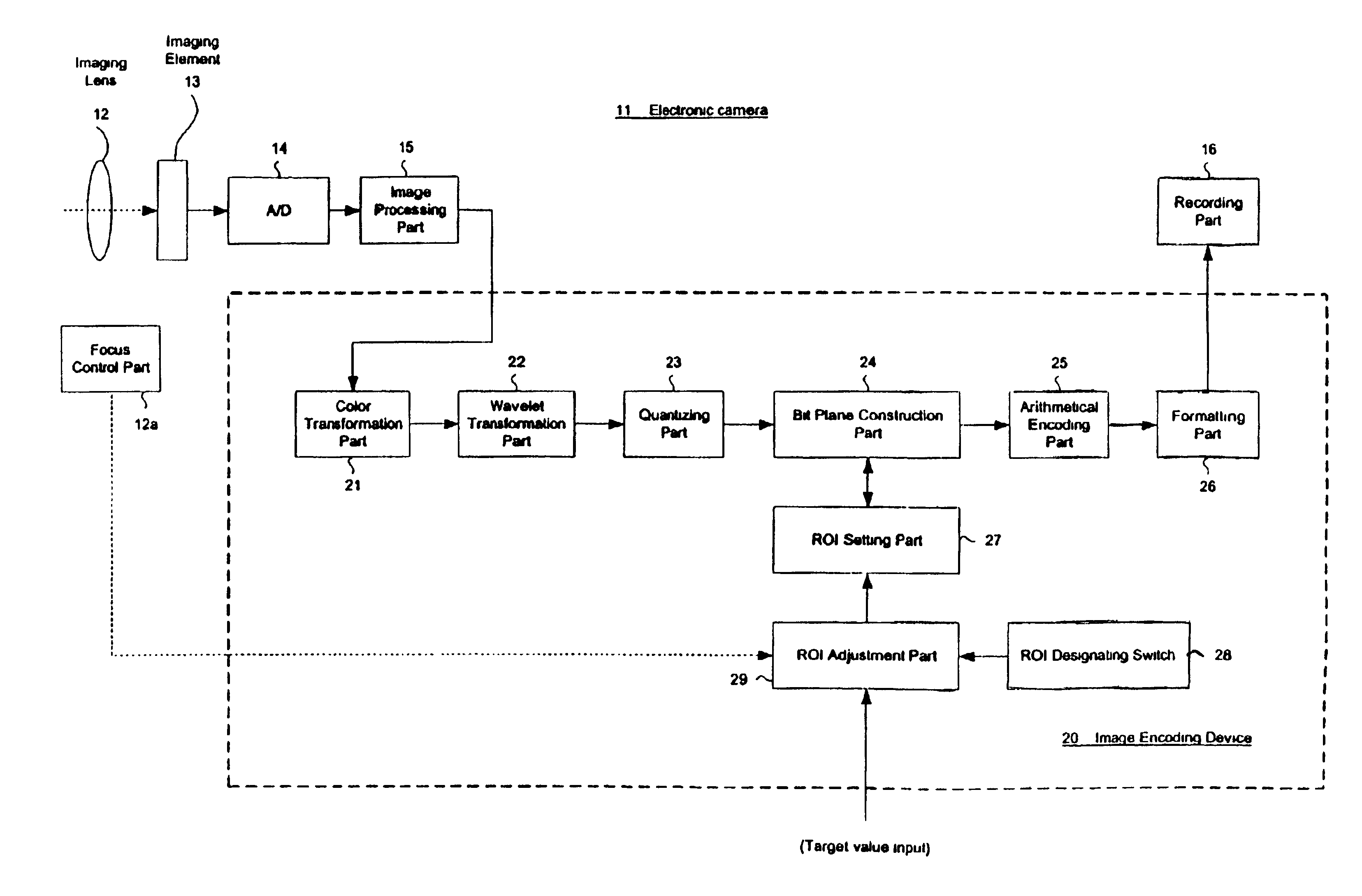
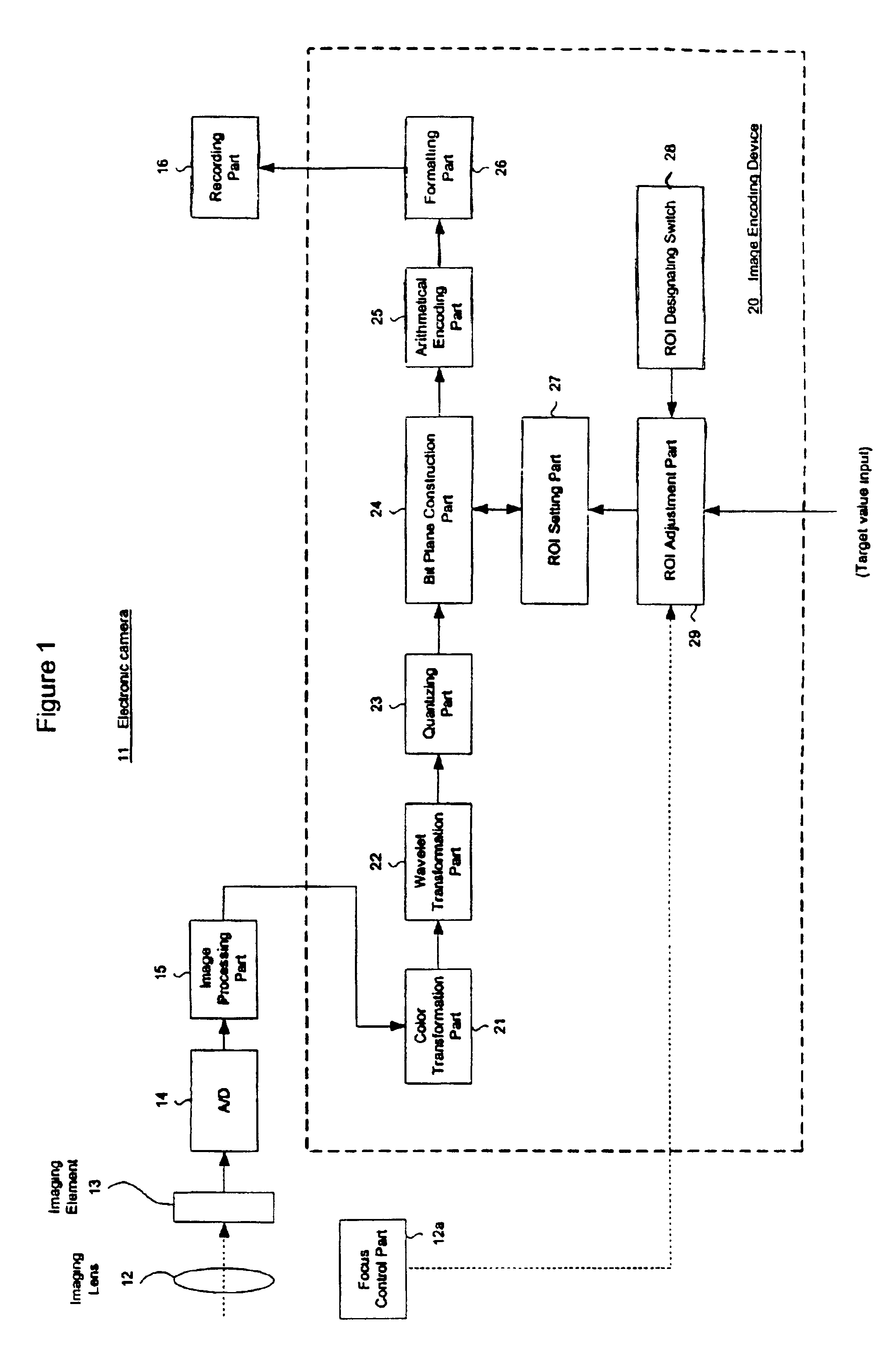
FIG. 1 is a block diagram which illustrates the construction of an electronic camera.
In FIG. 1, an imaging lens 12 is mounted on the electronic camera 11. The imaging plane of an imaging element 13 is disposed in the imaging space of imaging lens 12. The focus of imaging lens 12 is automatically controlled by a focus control part 12a, so that an image of the object of imaging is focused on the imaging plane of imaging element 13. Imaging element 13 subjects the image of the object of imaging to a photoelectric conversion, and outputs the result as an image signal. This image signal is digitized via an A/D converter part 14, and is then sent to an image processing part 15. Image processing part 15 performs image processing such as gradation conversion, black level correction and color interpolation processing on this image signal. Following this image processing, the image signal is sent to an image encoding device 20 inside electronic camera 11. Image encoding device 20 subjects the image signal to the compression and encoding stipulated by JPEG2000, and outputs a compressed image file. Recording part 16 acquires this image file and stores the image file on a recording medium such as a memory card.
The above-mentioned image encoding device 20 is constructed from the constituent elements discussed below.
(1) Color transformation part 21
(2) Wavelet transformation part 22
(3) Quantizing part 23
(4) Bit plane construction part 24
(5) Arithmetical encoding part 25
(6) Formatting part 26
(7) ROI setting part 27: A mask image indicating the selected region for ROI encoding is set. Bit plane construction part 24 divides the transformation coefficients into a selected region and non-selected region while referring to this mask image. Furthermore, bit plane construction part 24 allocates the quantity of information by shifting the transformation coefficients that have been divided into the selection region upward.
(8) ROI designating switch 28: This is a switch that allows the user to input the position and extent of the selected region. Specifically, this switch is constructed from a position input mechanism such as a cursor key or eye-control input device and a switch used to select the extent of the selected region.
(9) ROI adjustment part 29: This part determines the selected region in accordance with “the input values of ROI adjustment part 28” and the “target value input,” and sets the mask image in ROI setting part 27. Furthermore, ROI adjustment part acquires position information concerning the region of focus from the focus control part 12a, and adjust the position of the selected region so that the region of focus is included in the selected region as far as possible.
Description of Operation of First Working Configuration
FIG. 2 is a flow chart which illustrates the operation of the image encoding device according to the present invention, in a first working configuration. FIG. 3 is a diagram which illustrates the displacement of a selected region on the basis of the region of focus. Below, the operation of the first working configuration will be described in specific terms according to the operation steps shown in FIG. 2.
[Step S0] Here, color transformation part 21 acquires the image signal from the image processing part 15, and performs a color coordinate transformation as necessary, thus transforming the image signal into color components such as YCbCr.
[Step S1] Here, wavelet transformation part 22 performs a recursive wavelet transformation on the image signal following color coordinate transformation, thus producing transformation coefficients.
[Step S2] Here, quantizing part 23 quantizes the transformation coefficients as necessary.
[Step S3] Here, electronic camera 11 determines the following target values in accordance with the image quality selection (e.g., fine, basic) of the recording mode, and sends these values to the ROI adjustment part 29. Where,
γ total is the bit allocation rate of the image as a whole, and
γ roi is the bit allocation rate of the selected region.
In addition, γ total may be a value obtained by dividing the target file size following compression by the total area (e.g., total number of pixels) of the image. Moreover, γ roi may be a value that is statistically inferred from good image compression results obtained in the past.
[Step S4] Here, electronic camera 11 determines γ notroi_min in accordance with the image quality selection of the recording mode, and sends this value to the ROI adjustment part 29. The term γ notroi_min is the minimum guaranteed bit allocation rate in the non-selected region.
[Step S5] Here, ROI adjustment part 29 acquires the position and extent of the selected region via user input of the ROI designating switch 28. ROI adjustment part 29 calculates the area ratio Aroi_user of the selected region on the basis of this user input.
[Step S6] Here, ROI adjustment part 29 predicts the bit allocation rate γ notroi of the non-selected region on the basis of the following general approximate formula:
γnotroi=(γ total−γroi×Aroi_user)/(1−Aroi_user)  Equation 2
[Step S7] Here, ROI adjustment part 29 ascertains whether or not the predicted value γ notroi is less than the guaranteed value γ notroi_min.
If it is determined from the results of this ascertainment that the guaranteed value γ notroi_in can be sufficiently guaranteed by the area ratio Aroi_user (the NO side shown in FIG. 2), ROI adjustment part 29 shifts the operation to step S10.
On the other hand, if it is determined from the results of this ascertainment that the guaranteed value γ notroi_min cannot be guaranteed by the area ratio Aroi_user (the YES side shown in FIG. 2), ROI adjustment part 29 shifts the operation to step S8.
[Step S8] Here, ROI adjustment part 29 sets the guaranteed value γ notroi_min as the bit allocation rate γ notroi of the non-selected region, and takes this as a target value.
[Step S9] Here, ROI adjustment part 29 substitutes the target value into the following general approximate formula, and determines the area ratio Aroi:
Aroi=(γ total−γnotroi)/(γroi−γ notroi)  Equation 3
It should be noted that Equation 3 is obtained by modifying Equation 1 (discussed above).
After the area ratio Aroi has been determined, ROI adjustment part 29 shifts the operation to step S11.
[Step S10] Here, ROI adjustment part 29 sets the area ratio Aroi_user “as is” as the area ratio Aroi. The operation here corresponds to an operation in which the area ratio Aroi is limited with the area ratio Aroi_user as the upper limit. Thus, it is desirable that the user make a user input of the maximum selected region so that the entire object of interest is included.
[Step S11] Here, ROI adjustment part 29 acquires the selected position of the focus detection area from focus control part 12a. ROI adjustment part 29 detects the region of focus on the basis of this acquired information, and displaces the selected region in the direction of this region of focus, as shown in FIG. 3.
[Step S12] Here, ROI adjustment part 29 produces a mask image on the basis of the position and area ratio Aroi of the selected region determined thus far. ROI adjustment part 29 sets this mask image in the ROI setting part 27.
Moreover, bit plane construction part 24 divides the transformation coefficients into regions while referring to the mask image of the ROI setting part 27, and performs bit plane encoding while allocating a greater quantity of information to the selected region. Arithmetical encoding part 25 performs arithmetical encoding on the data following bit plane encoding.
[Step S13] Here, formatting part 26 arranges the arithmetically encoded data according to SNR progressive, and thus produces a bit stream. Additionally formatting part 26 cuts the bit stream using the target file size.
Therefore, image encoding according to JPEG2000 is completed as a result of the series of operations discussed above.
Effects. etc., of the First Working Configuration
In the first working configuration, as described above, the area ratio Aroi of the selected region is adjusted on the basis of:
(1) the bit allocation rate γ total of the image as a whole,
(2) the bit allocation rate γ roi of the selected region,
(3) the bit allocation rate γ notroi of the non-selected region, and
(4) the area ratio Aroi_user designated by the user.
As a result, the area of the selected region is appropriately adjusted, so that a compressed image file in which the image quality balance between the selected region and the non-selected region is favorably maintained can be produced.
Moreover, in the first working configuration, the position of the selected region is determined on basis of the position of the region of focus. As a result, ROI encoding can be performed so that the important region on the image known as the region of focus is included, thus making it possible to produce an even more favorable compressed image file.
Next, a second working configuration will be described.
Description of Operation of Second Working Configuration
The second working configuration is another working configuration of an electronic camera according to the present invention.
The construction of the electronic camera of the second working configuration is similar to that of the first working configuration (e.g., FIG. 1). Accordingly, FIG. 1 will be referred to “as is” here, and a description of the construction will be omitted.
FIG. 4 is a flow chart which illustrates the operation of the image encoding device according to the present invention, in the second working configuration. Below, the operation of the image encoding device will be described according to the operating steps shown in FIG. 4.
[Steps S0 to S2] These steps are the same as in the first working configuration.
[Step S20] Here, electronic camera 11 determines the following target values in accordance with the image quality selection (e.g., fine, basic) of the recording mode, and sends the results to ROI adjustment part 29. Where,
γ total is the bit allocation rate of the image as a whole, and
γ notroi is the bit allocation rate of the non-selected region.
Furthermore, γ total may be a value obtained by dividing the target file size following compression by the total area (e.g., total number of pixels) of the image. Moreover, γ notroi may be a value that is statistically inferred from favorable image compression results obtained in the past.
[Step S21] Here, electronic camera 11 determines γ roi_max in accordance with the image quality selection of the recording mode, and sends the result to ROI adjustment part 29. Where,
γ roi_max is the upper-limit value of the bit allocation rate of the selected region.
Moreover, γ roi—max may also be a value that is statistically inferred from favorable image compression results obtained in the past.
[Step S22] Here, ROI adjustment part 29 acquires the position and extent of the selected region via user input of ROI designating switch 28. ROI adjustment part 29 calculates the area ratio Aroi of the selected region on the basis of the extent of this selected region, and sets this value as a target value.
[Step S23] Here, ROI adjustment part 29 calculates the bit allocation rate γ roi of the selected region by substituting the target values into the following general approximate formula:
γroi=[γ total−γnotroi×(1−Aroi)]/Aroi Equation 4
It should be noted that Equation 4 is obtained by modifying Equation 1 (discussed above).
[Step S24] Here, ROI adjustment part 29 determines whether or not the bit allocation rate γ roi is less than the upper-limit value γ roi_Max. In cases where the bit allocation rate γ roi exceeds the upper-limit value γ roi_max, ROI adjustment part 29 determines that bit allocation rate γ roi is excessive and that this bit allocation rate will destroy the image quality balance between the selected region and non-selected region. Thus, ROI adjustment part 29 shifts the operation to step S25.
On the other hand, in cases where the bit allocation rate γ roi is less than the upper-limit value γ roi_Max, ROI adjustment part 29 determines that bit allocation rate γ roi is suitable, and shifts the operation to step S26.
[Step S25] Here, ROI adjustment part 29 limits the bit allocation rate γ roi to the upper-limit value γ roi_max.
[Step S26] Here, ROI adjustment part 29 acquires the selected position of the focus detection area from focus control part 12a. ROI adjustment part 29 detects the region of focus on the basis of this acquired information, and displaces the selected region in the direction of this region of focus, as shown in FIG. 3.
[Step S27] Here, ROI adjustment part 29 produces a mask image on the basis of the position and area ratio Aroi of the selected region determined thus far. ROI adjustment part 29 sets this mask image in the ROI setting part 27.
Moreover, bit plane construction part 24 divides the transformation coefficients into regions while referring to the mask image of ROI setting part 27, and performs bit plane encoding while allocating a greater quantity of information to the selected region by bit-shifting transformation coefficients of the selected region upward. Arithmetical encoding part 25 performs arithmetical encoding of the data following bit plane encoding.
[Step S28] Here, formatting part 26 produces a bit stream by arranging the arithmetically encoded data according to SNR progressive.
Additionally, the formatting part 26 cuts the bit stream of the selected region at the stage where the bit stream of the selected region exceeds the code quantity Qroi of the following equation:
Qroi=γ roi×Aroi×(total number of pixels of the image as a whole)  Equation 5
Furthermore, formatting part 26 cuts the overall bit stream at the stage where this bit stream exceeds the target file size.
Therefore, image encoding according to JPEG2000 is completed as a result of the above-mentioned series of operations.
Effects. etc., of the Second Working Configuration
In the second working configuration, as described above, the bit allocation rate γ roi of the selected region is adjusted on the basis of:
(1) the bit allocation rate γ total of the image as a whole,
(2) the area ratio Aroi of the selected region according to the designation of the user, and
(3) the bit allocation rate γ notroi of the non-selected region.
As a result, the bit allocation rate of the selected region can be appropriately adjusted and manipulated, so that a compressed image file can be produced in which the image quality balance between the selected region and the non-selected region is favorably maintained.
Furthermore, in the second working configuration, the position of the selected region is determined on basis of the position of the region of focus. As a result, ROI encoding can be performed so that the important region on the image known as the region of focus is included, thus making it possible to produce an even more favorable compressed image file.
Next, a third working configuration will be described.
Description of Operation of Third Working Configuration
The third working configuration is yet another working configuration of an electronic camera according to the present invention.
Moreover, the construction of the third working configuration is similar to that of the first working configuration (e.g., FIG. 1). Accordingly, FIG. 1 will be referred to “as is,” and a description of the construction will be omitted.
FIG. 5 is a flow chart which illustrates the operation of the image encoding device according to the present invention, in the third working configuration. Below, this operation will be described according to the operation steps shown in FIG. 5.
[Step S0 to S2] These steps are the same as in the first working configuration.
[Step S30] Here, electronic camera 11 determines the following target values in accordance with the image quality selection (e.g., fine, basic) of the recording mode, and sends the results to ROI adjustment part 29. The term γ total is the bit allocation rate of the image as a whole, and K is the ratio of bit allocation rates of both regions (corresponds to γ roi/γ notroi).
Furthermore, γ total may be a value obtained by dividing the target file size following compression by the total area (e.g., total number of pixels) of the image. Moreover, K may be a value that is statistically inferred from favorable image compression results obtained in the past.
[Step S31] Here, ROI adjustment part 29 acquires the position and extent of the selected region via user input of ROI designating switch 28. ROI adjustment part 29 calculates the area ratio Aroi of the selected region on the basis of the extent of this selected region, and sets this value as a target value.
[Step S32] Here, ROI adjustment part 29 calculates the bit allocation rate γ roi of the selected region by substituting the target values into the following general approximate formula:
γroi=γ total×K/[1+(K−1)Aroi] Equation 6
It should be noted that Equation 6 is obtained by modifying Equation 1 (discussed above).
[Step S33] Here, ROI adjustment part 29 limits the bit allocation rate γ roi using an upper-limit value and a lower-limit value. The upper-limit value and lower-limit value may be statistically inferred from favorable image compression results obtained in the past.
[Step S34] Here, ROI adjustment part 29 acquires the selected position of the focus detection area from focus control part 12a. ROI adjustment part 29 detects the region of focus on the basis of this acquired information, and displaces the selected region in the direction of this region of focus, as shown in FIG. 3.
[Step S35] Here, ROI adjustment part 29 produces a mask image on the basis of the position and area ratio Aroi of the selected region determined thus far. ROI adjustment part 29 sets this mask image in the ROI setting part 27.
Moreover, bit plane construction part 24 divides the transformation coefficients into regions while referring to the mask image of ROI setting part 27, and performs bit plane encoding while allocating a greater quantity of information to the selected region by bit-shifting transformation coefficients of the selected region upward. Arithmetical encoding part 25 performs arithmetical encoding of the data following bit plane encoding.
[Step S36] Here, formatting part 26 produces a bit stream by arranging the arithmetically encoded data according to SNR progressive.
Additionally formatting part 26 cuts the bit stream of the selected region at the stage where the bit stream of the selected region exceeds the code quantity Qroi of the following equation:
Qroi=γ roi×Aroi×(total number of pixels of the image as a whole)  Equation 7
Furthermore, formatting part 26 cuts the overall bit stream at the stage where this bit stream exceeds the target file size.
Therefore, image encoding according to JPEG2000 is completed as a result of the above-mentioned series of operations.
Effects. etc. of the Third Working Configuration
In the third working configuration, as described above, the bit allocation rate γ roi of the selected region is adjusted on the basis of:
(1) the bit allocation rate γ total of the image as a whole,
(2) the area ratio Aroi of the selected region according to the designation of the user, and
(3) the ratio K of the bit allocation rates of both regions.
As a result, the bit allocation rate of the selected region can be appropriately adjusted and manipulated, so that a compressed image file in which the image quality balance between the selected region and the non-selected region is favorably maintained, can be produced.
In particular, in the third working configuration, the “ratio K of the bit allocation rates of both regions” is used as a target value. This ratio K is a value that directly expresses the image quality balance of both regions. Accordingly, the image quality balance of the two regions can be directly controlled by using this ratio K as a target value.
Furthermore, in the third working configuration, the position of the selected region is determined on the basis of the position of the region of focus. As a result, ROI encoding can be performed so that the important region on the image known as the region of focus is included, thus making it possible to produce an even more favorable compressed image file.
Next, a fourth working configuration will be described.
Description of Operation of Fourth Working Configuration
The fourth working configuration is yet another working configuration of an electronic camera according to the present invention.
Moreover, the construction of the fourth working configuration is similar to the construction of the first working configuration (e.g., FIG. 1). Accordingly, FIG. 1 will be referred to “as is” here, and a description of the construction will be omitted.
As shown in FIGS. 6A-6F, the characterizing feature of the operation of the fourth working configuration is that the bit allocation rate of the selected region is varied in multiple stages. The remaining operation is the same as that in the first through third working configurations, discussed above. Accordingly, a description of this remaining operation is omitted here.
Thus, the characterizing feature of such an operation will be described in detail below.
Multi-Stage Variation of the Bit Allocation rate
In the fourth working configuration, as is shown in FIGS. 6A-6F, a region of greatest importance is disposed within the selected region. This region of greatest importance is a region to which a greater quantity of data is allocated with a special preference even within the selected region. On the other hand, in the periphery of the selected region, the quantity of information is allocated more moderately even within the selected region, so that the difference between this periphery of the selected region and the non-selected region is not conspicuous.
As a result, the bit allocation rate varies in multiple stages from the peripheral part of the selected region toward the region of greatest importance.
Means Used to Realize Multi-Stage Variation
Such a multi-stage variation in the bit allocation rate is realized by the operation discussed below.
First, ROI adjustment part 29 adjusts the selected region. On the basis of the results of this adjustment operation, ROI adjustment part 29 produces a multi-value mask image which indicates a multi-stage bit allocation rate in pixel units, and sets this mask image in ROI setting part 27.
Next, the multi-stage variation of the bit allocation rate is specifically executed by at least one of the component described below. Quantizing part 23 determines multiple stages of quantizing steps while referring to the mask image, and quantizes the transformation coefficients in multiple stages. Bit plane construction part 24 determines multiple stages of bit shift numbers while referring to the mask image, and shifts the transformation coefficients upward in multiple stages. Formatting part 26 cuts the bit stream in multiple stages in accordance with the reference value (bit allocation rate) of the mask image.
Additionally, the formatting part 26 includes the above-mentioned multi-value mask image in the compressed image file. As a result, this mask image can also be used in decoding the compressed image file.
Rough Adjustment of the Selected Region
If such a multi-stage bit allocation rate is expressed in the form of a bit allocation rate W(x, y) at a position (x, y), then the average bit allocation rate γ roi_ave for the selected region is as follows: γ ⁢ ⁢ roi ⁢ ⁢ _ ⁢ ⁢ ave = ∑ x , y ∈ ROI ⁢ W ⁡ ( x , y ) / Nroi Equation  8
(Here, Nroi is the number of pixels of the selected region.)
Accordingly, a rough adjustment of the selected region can be accomplished in the same manner as in the first through third working configurations, discussed above, by using this average bit allocation rate γ roi_ave instead of the bit allocation rate γ roi used in the first through third working configurations.
Fine Variations of the Adjustment Operation of the Selected Region
By utilizing the degree of freedom of the bit allocation rate, ROI adjustment part 29 can apply the fine variations to the adjustment of the selected region, as discussed below.
[A] As shown in FIG. 6A, in area adjustment of the selected region, ROI adjustment part 29 adjusts the areas of the selected region and region of greatest importance at a fixed ratio. In this case, the slope of increase of the bit allocation rate is also adjusted. Such an area adjustment is suitable for use in cases where the quantity of information allocated to the selected region is greatly adjusted.
[B] As shown in FIG. 6B, in area adjustment of the selected region, ROI adjustment part 29 keeps the area of the region of greatest importance constant, and adjusts the area of the selected region. In this case, the slope of increase of the bit allocation rate is also adjusted. Such an area adjustment is suitable for use in cases where the region of greatest importance cannot be altered, such as cases in which the region of greatest importance is set in accordance with the size of the object of imaging.
[C] As shown in FIG. 6C, in area adjustment of the selected region, ROI adjustment part 29 keeps the area of the selected region constant, and adjusts the area of the region of greatest importance. In this case, the slope of increase of the bit allocation rate is also adjusted. Such an area adjustment is suitable for use in cases where the selected region cannot be altered, such as cases in which the selected region is set in accordance with the size of the object of imaging.
[D] As shown in FIG. 6D, in area adjustment of the selected region, ROI adjustment part 29 adjusts the areas of both the selected region and the region of greatest importance while keeping the slope of the bit allocation rate at a constant value. In this case, since the slope of the bit allocation rate is maintained at a constant value, this adjustment operation is suitable for use in cases where it is desired to prevent the boundary between the selected region and the non-selected region from becoming noticeable.
[E] As shown in FIG. 6E, in adjustment of the bit allocation rate, ROI adjustment part 29 adjusts the maximum bit allocation rate of the region of greatest importance while maintaining the slope of the bit allocation rate at a constant value. In this case, the area of the selected region is adjusted as a result. Furthermore, since the slope of the bit allocation rate is maintained at a constant value in this case, this adjustment operation is suitable for use in cases where it is desired to prevent the boundary between the selected region and the non-selected region from becoming noticeable.
[F] As shown in FIG. 6F, in adjustment of the bit allocation rate, ROI adjustment part 29 adjusts the maximum bit allocation rate of the region of greatest importance while maintaining the area of the selected region at a constant value. In this case, the slope of the bit allocation rate is also adjusted. Such an adjustment of the bit allocation rate is an adjustment operation suitable for use in cases where the selected region cannot be altered, such as cases in which the selected region is set in accordance with the size of the object of imaging.
It should be noted that more specific and diverse variations can be applied to the adjustment operation of the selected region by performing the above-mentioned area adjustments A through D (FIGS. 6A-6D) in combination with the bit allocation rate adjustments E and F (FIGS. 6E-6F).
Items Supplementary to the Working Configurations
In the above-mentioned first through fourth working configurations, the image is transformed into transformation coefficients by performing a wavelet transformation. However, the present invention is not limited to such a transformation. In general, it is sufficient if the image is transformed into transformation coefficients using frequency decomposition.
For example, orthogonal transformations such as a discrete cosine transformation, discrete Fourier transformation, Hadamard transformation or Karhunen-Loeve transformation can be used. In the case of such orthogonal transformations, it is desirable that the image be divided into the selected region and non-selected region using the minimum processing blocks of the orthogonal transformation as units.
Furthermore, the image may also be transformed into transformation coefficients by sub-band decomposition. Besides wavelet transformation, such sub-band decomposition also includes pyramid-hierarchical encoding.
Additionally, in the above-mentioned first through fourth working configurations, the bit allocation rate of the selected region is controlled by cutting the bit stream. However, the present invention is not limited to this. For example, it would also be possible to control the bit allocation rate of the selected region by using the quantizing part 23 to adjust the quantizing steps of the selected region. Alternatively, it would also be possible to control the bit allocation rate of the selected region by using bit plane construction part 24 to adjust the bit shift number of the selected region.
Moreover, in the above-mentioned working configurations, it would also be possible to adjust area ratio Aroi of the selected region using:
(1) the bit allocation rate γ total of the image as a whole,
(2) the bit allocation rate γ roi of the selected region, and
(3) the ratio K of the bit allocation rates of both regions, as target values, as discussed above.
Furthermore, area ratio Aroi of the selected region may also be determined by substituting these target values into the following equation, as discussed above.
Aroi=(K×γ total/γroi×1)/(K×1)  Equation 9
It should be noted that Equation 9 is obtained by modifying Equation 1 (discussed above).
Additionally, in the above-mentioned working configurations, it would also be possible to limit area ratio Aroi in accordance with at least an upper-limit value or a lower-limit value (or both). Such an upper-limit value and lower-limit value may be values that are statistically inferred from favorable image compression results that have been obtained in the past. As a result of such limits, the danger that the area ratio Aroi will be set as a biased value is eliminated, so that the area of the ROI region can be adjusted much more appropriately.
Moreover, in the above-mentioned working configurations, bit allocation rate γ roi may also be limited in accordance with at least an upper-limit value or a lower-limit value (or both). Such an upper-limit value and lower-limit value may be values that are statistically inferred from favorable image compression results that have been obtained in the past. As a result of such limits, the danger that the bit allocation rate γ roi will be set as a biased value is eliminated, so that the bit allocation rate γ roi can be adjusted much more appropriately.
Furthermore, in the above-mentioned working configurations, the region of focus is detected on basis of the selection of the focus detection area. However, the present invention is not limited to this. For example, it would also be possible to detect the region of focus on the image by contrast detection or space frequency analysis of the image.
Additionally, in the above-mentioned working configurations, the selected region is displaced in the direction of the region of focus. This is advantageous in that the position of the selected region can be flexibly determined while taking into account both the designation of the user and the region of focus. However, the present invention is not limited to this. For example, it would also be possible to set the position of the selected region with the region of focus at the center. Furthermore, the position and extent of the selected region may be adjusted so that the region of focus is included to the maximum extent possible.
Moreover, in the above-mentioned working configurations, although designation of the selected region by the user is viewed with importance, the selected region is appropriately varied in accordance with the target values. This is advantageous in that the selected region can be skillfully adjusted while taking into account both the designation of the user and the target values. However, the present invention is not limited to this. For example, it would also be possible to install an operating mode in which the selected region is set “as is” in accordance with the designation of the user. Furthermore, an operating mode in which the selected region is set on basis of image information may also be installed.
Furthermore, in the above-mentioned first through fourth working configurations, a space frequency low-pass treatment may be applied to the non-selected region, as discussed above. For example, ROI adjustment part 29 determines the selected region prior to frequency decomposition of the image (steps S0 to S2). Next, ROI adjustment part 29 discriminates the non-selected region from the image prior to frequency decomposition, and performs a space frequency low-pass treatment such as Gauss gradation on this non-selected region. In regard to the low-pass characteristics in this case, it is desirable that high-band signal components that are lost in high-efficiency encoding be suppressed beforehand. As a result of such a treatment, the deterioration in image quality that occurs in high-efficiency encoding is reduced, thus making the noise of the decoded image unnoticeable.
Additionally, in the above-mentioned working configurations, an electronic camera 11 on which an image encoding device 20 is mounted was described. However, the present invention is not limited to an electronic camera. More broadly, present invention is a technique that can be used in image encoding in general.
For example, an image encoding program for executing the operations of the above-mentioned working configurations in a computer can be prepared. The recording medium discussed above can be obtained by recording this image encoding program on a recording medium.
Moreover, operation of the present invention in regard to the above-mentioned program and program recording medium is not limited by the above-mentioned working configurations. For example, such a program may be distributed via communications circuits, and the program may be recorded for example, in a system memory or a hard disk of the destination computer. By such program distribution, the program distribution source can manufacture the program or program recording medium in destination locations. Moreover, by such program distribution, the distribution source can transfer the program or program recording medium to the destinations. Furthermore, the fact that the program can be distributed may be published via a communications circuit, and a service which provides information on the program storage location may be performed.
Effect of the Invention
In the image encoding device according to the present invention, the area of the selected region is adjusted when the selected region is designated. In fixed-length compression, such an area adjustment makes it possible to control the quantity of information that is distributed to the non-selected region. As a result, the image quality balance between the selected region and the non-selected region can be controlled to a desired state.
Furthermore, in the image encoding device according to the present invention, the area of the selected region is adjusted on basis of the “bit allocation rate of the image as a whole,”“bit allocation rate of the selected region” and “bit allocation rate of the non-selected region,” which are pre-determined as target values. Accordingly, the area of the selected region can be quickly determined without any illogical adjustment of the area of the selected region.
Additionally, in the image encoding device according to the present invention, the area of the selected region is adjusted on basis of the “bit allocation rate of the image as a whole,”“bit allocation rate of the selected region” and “ratio of the bit allocation rates of both regions,” which are given beforehand as target values. Accordingly, the area of the selected region can be quickly determined without any illogical adjustment of the area of the selected region.
Moreover, in the image encoding device according to the present invention, the area of the selected region can easily be determined by substituting the target values into Equation 1.
Furthermore, in the image encoding device according to the present invention, an adjustment operation is performed with an upper limit and lower limit applied to the area of the selected region. Accordingly, there is no danger that the selected region will be adjusted to an illogical area.
For example, a case may be envisioned in which the quantity of image information contained in the non-selected region is small to begin with, so that the bit allocation rate of the non-selected region cannot be effectively raised regardless of how far the area of the selected region is narrowed. In such a case, unnecessary narrowing of the area of the selected region can be avoided by applying a lower limit to the area of the selected region.
Additionally, a case may also be envisioned in which the quantity of image information in the image as a whole is small to begin with, so that the bit allocation rate of the non-selected region cannot be effectively lowered regardless of how far the area of the selected region is expanded. In such a case, unnecessary expansion of the area of the selected region can be avoided by applying an upper limit to the area of the selected region.
Moreover, in the image encoding device according to the present invention, the bit allocation rate of the selected region is adjusted when the selected region is designated. In fixed-length compression, the bit allocation rate of the non-selected region can be controlled by such an adjustment. As a result, the image quality balance between the selected region and the non-selected region can be controlled to a desired state.
Furthermore, in the image encoding device according to the present invention, the bit allocation rate of the selected region is adjusted on basis of the “bit allocation rate of the image as a whole,”“area of the selected region” and “bit allocation rate of the non-selected region,” which are pre-determined as target values. Accordingly, the bit allocation rate of the selected region can be quickly determined without any illogical adjustment of the bit allocation rate of the selected region.
Additionally, in the image encoding device according to the present invention, the bit allocation rate of the selected region is adjusted on basis of the “bit allocation rate of the image as a whole,”“area of the selected region” and “ratio of the bit allocation rates of both regions,” which are pre-determined as target values. Accordingly, the bit allocation rate of the selected region can be quickly determined without any illogical adjustment of the bit allocation rate of the selected region.
Moreover, in the image encoding device according to the present invention, the bit allocation rate of the selected region can easily be determined by substituting the target values into Equation 1.
Furthermore, in the image encoding device according to the present invention, an adjustment operation is performed with an upper limit and lower limit applied to the bit allocation rate of the selected region. Accordingly, there is no danger that the selected region will be adjusted to an illogical bit allocation rate.
For example, a case may be envisioned in which the amount of image information contained in the non-selected region is small to begin with, so that the bit allocation rate of the non-selected region cannot be effectively raised regardless of how far the bit allocation rate of the selected region is lowered. In such a case, unnecessary lowering of the bit allocation rate of the selected region can be avoided by applying a lower limit to the bit allocation rate of the selected region.
Additionally, a case may also be envisioned in which the amount of image information contained in the selected region is small to begin with, so that the bit allocation rate of the selected region does not actually rise regardless of how high the bit allocation rate of the selected region is set. In such a case, setting the bit allocation rate of the selected region at an unnecessarily high value can be avoided by applying an upper limit to the bit allocation rate of the selected region.
Moreover, in the image encoding device according to the present invention, the slope of increase of the quantity of information allocated to the selected region is adjusted when the selected region is designated. In fixed-length compression, the quantity of information distributed to the non-selected region can be controlled by means of such an adjustment. As a result, the image quality balance between the selected region and the non-selected region can be controlled to a desired state.
Furthermore, in the image encoding device according to the present invention, the maximum value of the bit allocation rate allocated to the selected region is adjusted when the selected region is designated. In fixed-length compression, the quantity of information distributed to the non-selected region can be controlled by means of such an adjustment. As a result, image quality balance between the selected region and the non-selected region can be controlled to a desired state.
Additionally, in the image encoding device according to the present invention, the selected region is determined on basis of the region of focus of the image. Accordingly, the selected region, known as the region of focus, can be appropriately designated in accordance with the major interest of the user.
Moreover, in the image encoding device according to the present invention, the selected region is displaced in direction of the region of focus of the image when the selected region is designated. As a result, the selected region, known as the region of focus, can be skillfully adjusted so that this region approaches the major interest of the user.
Furthermore, in the image encoding device according to the present invention, the selected region is designated according to the designating input of the user. Accordingly, the user can freely set the selected region in accordance with the desired position, size or shape.
Additionally, in the image encoding device according to the present invention, a space frequency low-pass treatment is performed on the non-selected region. For example, in cases where a space frequency low-pass treatment is performed on the non-selected region prior to encoding, the high-band signal components that are lost as a result of high-efficiency encoding of the non-selected region are reduced in advance, so that deterioration in the image quality of the non-selected region can be prevented from becoming noticeable.
Next, an electronic camera can be constructed equipped with the image encoding device according to the present invention.
Finally, the image encoding device according to the present invention can be realized in a computer.
Although the foregoing description is directed to the preferred embodiments of the invention, it is noted that other variations and modifications will be apparent to those skilled in the art, and may be made without departing from the spirit or scope of the invention.

PUM

no PUM

Description & Claims & Application Information

We can also present the details of the Description, Claims and Application information to help users get a comprehensive understanding of the technical details of the patent, such as background art, summary of invention, brief description of drawings, description of embodiments, and other original content. On the other hand, users can also determine the specific scope of protection of the technology through the list of claims; as well as understand the changes in the life cycle of the technology with the presentation of the patent timeline. Login to view more.

Similar technology patents

Data communications

ActiveUS20110019575A1rate be control
Owner:BT NEWGATE

Eggshell disinfectant system

InactiveUS20110253050A1rate be control
Owner:ABRAMOV EREZ

Germicidal air diffuser

PendingUS20220290883A1rate be control
Owner:RICKARD AIR DIFFUSION

Transdermal dosage form for low-melting point active agent

ActiveUS20140188057A1improved physical performancerate be control
Owner:MYLAN

Marine biodegradable composition for 3-D printing

ActiveUS10752772B1rate be control
Owner:USA REPRESENTED BY THE SEC OF THE NAVY

Classification and recommendation of technical efficacy words

  • rate be control

Liquid flow control for film deposition

ActiveUS20130233395A1rate be control
Owner:MSP

Session transfer by tunnel endpoint identifier renumbering

InactiveUS20170251514A1rate be control
Owner:NOKIA SOLUTIONS & NETWORKS OY

Transdermal dosage form for low-melting point active agent

ActiveUS20140188057A1improved physical performancerate be control
Owner:MYLAN

Data communications

ActiveUS20110019575A1rate be control
Owner:BT NEWGATE

Eggshell disinfectant system

InactiveUS20110253050A1rate be control
Owner:ABRAMOV EREZ
Why Eureka
Try Eureka