Pneumatic tire

a pneumatic tire and tire reinforcement technology, applied in the field of tires, can solve the problems of increasing the weight of the tire, affecting the rolling resistance of the tire, and affecting the cost of a rough rid

Inactive Publication Date: 2012-06-14
FELTES SERGE GUILLAUME +2
View PDF2 Cites 11 Cited by
  • Summary
  • Abstract
  • Description
  • Claims
  • Application Information

AI Technical Summary

Problems solved by technology

For example, since the apex extends up much of the length of the sidewall, increasing the stiffness of the apex increases the stiffness of the sidewall, yielding less sidewall flexing and hence less flexural heat and material fatigue, but at the cost of a rougher ride.
The use of compound apexes unfortunately can add to increased tire weight, and thus negatively impact tire rolling resistance.

Method used


Image

  • Pneumatic tire
  • Pneumatic tire
  • Pneumatic tire

Examples


Embodiment Construction

[0022]The following language is of the best presently contemplated mode or modes of carrying out the invention. This description is made for the purpose of illustrating the general principals of the invention and should not be taken in a limiting sense. The scope of the invention is best determined by reference to the appended claims.

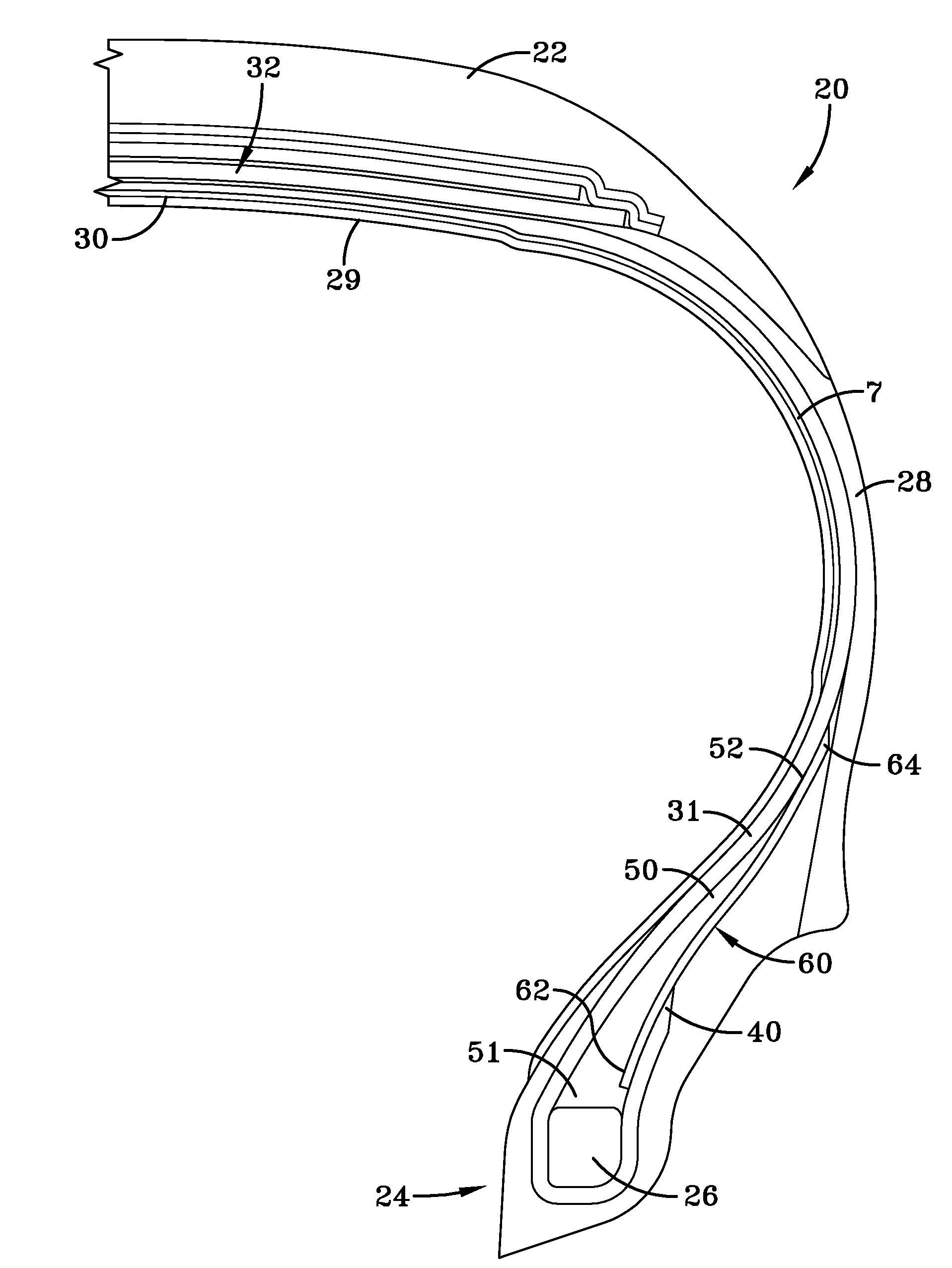
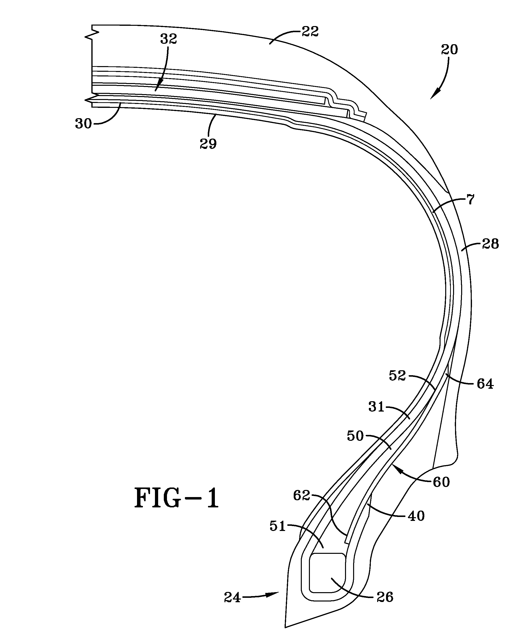
[0023]FIG. 1 illustrates a cross-sectional view of one half of a radial tire 20 of the present invention. The tire is symmetrical about the mid-circumferential plane so that only one half of the tire is illustrated. Alternatively, the tire may also be an asymmetric tire. The tire 20 as depicted is a passenger tire, but the disclosed invention may be applicable for light truck tires, radial medium truck tires, heavy load tires, industrial tires, off-the-road tires, or other types of tires. One skilled in the art will appreciate that for each type of tire, the internal construction, the tread configuration, and materials of construction will be selected f...


PUM


Abstract

A pneumatic tire having a carcass and a belt reinforcing structure is disclosed. The carcass comprising at least one inner ply which is wound around an annular bead member and extends radially outward towards the crown forming a turnup end; said tire further including a rubber apex located radially outward of said bead and having a radially outer end, wherein said turnup end is located radially outward of said rubber apex, and a reinforcement member having a first end and a second end, wherein the first end is positioned adjacent said apex, and the second end is radially outward of the apex outer end.

Description

CROSS REFERENCE TO OTHER APPLICATIONS [0001]This application claims the benefit of and incorporates by reference U.S. Provisional Application No. 61 / 421,837, filed Dec. 10, 2010.FIELD OF THE INVENTION [0002]The present invention is directed to a tire. More specifically, the present invention is directed to a tire suitable for use as a passenger tire.BACKGROUND OF THE INVENTION [0003]A conventional radial-ply automobile tire includes radial plies that are wrapped around two annular inextensible beads. In the tire making process, a green tire carcass (“green” meaning as yet uncured and still tacky) is built by sliding a green innerliner and radial ply over a tire “building drum” (or “building mandrel”). Two beads (each comprising a cable of steel filaments encased in green rubber) are then slid over the carcass, one at each side. The portions of the plies that extend beyond the beads are then turned up around the beads, forming “turn-ups”. Then, the portion of the plies between the be...

Claims


Application Information

Patent Timeline
Patent Type & Authority Applications(United States)
IPC IPC(8): B60C15/06B60C15/00B60C9/16B60C9/02
CPCB60C15/06B60C15/0027B60C2015/009B60C9/08B60C15/00B60C15/04
Inventor FELTES, SERGE GUILLAUMEHOLTZMER, MARCHANSEN, ROMAIN FERNAND
Owner FELTES SERGE GUILLAUME
Why Eureka
Try Eureka