Image reading apparatus, control method thereof, and recording medium

a technology of image reading and control method, applied in the direction of electrical apparatus, picture communication, etc., can solve the problems of difficult to sufficiently reduce the influence, long time for reading original documents, and limited operation, and achieve the effect of the same operation

a technology of image reading and control method, applied in the direction of electrical apparatus, picture communication, etc., can solve the problems of difficult to sufficiently reduce the influence, long time for reading original documents, and limited operation, and achieve the effect of the same operation

US20120147439A1Active Publication Date: 2012-06-14SEIKO EPSON CORP

Image

  • Image reading apparatus, control method thereof, and recording medium
  • Image reading apparatus, control method thereof, and recording medium
  • Image reading apparatus, control method thereof, and recording medium

Examples


Embodiment Construction

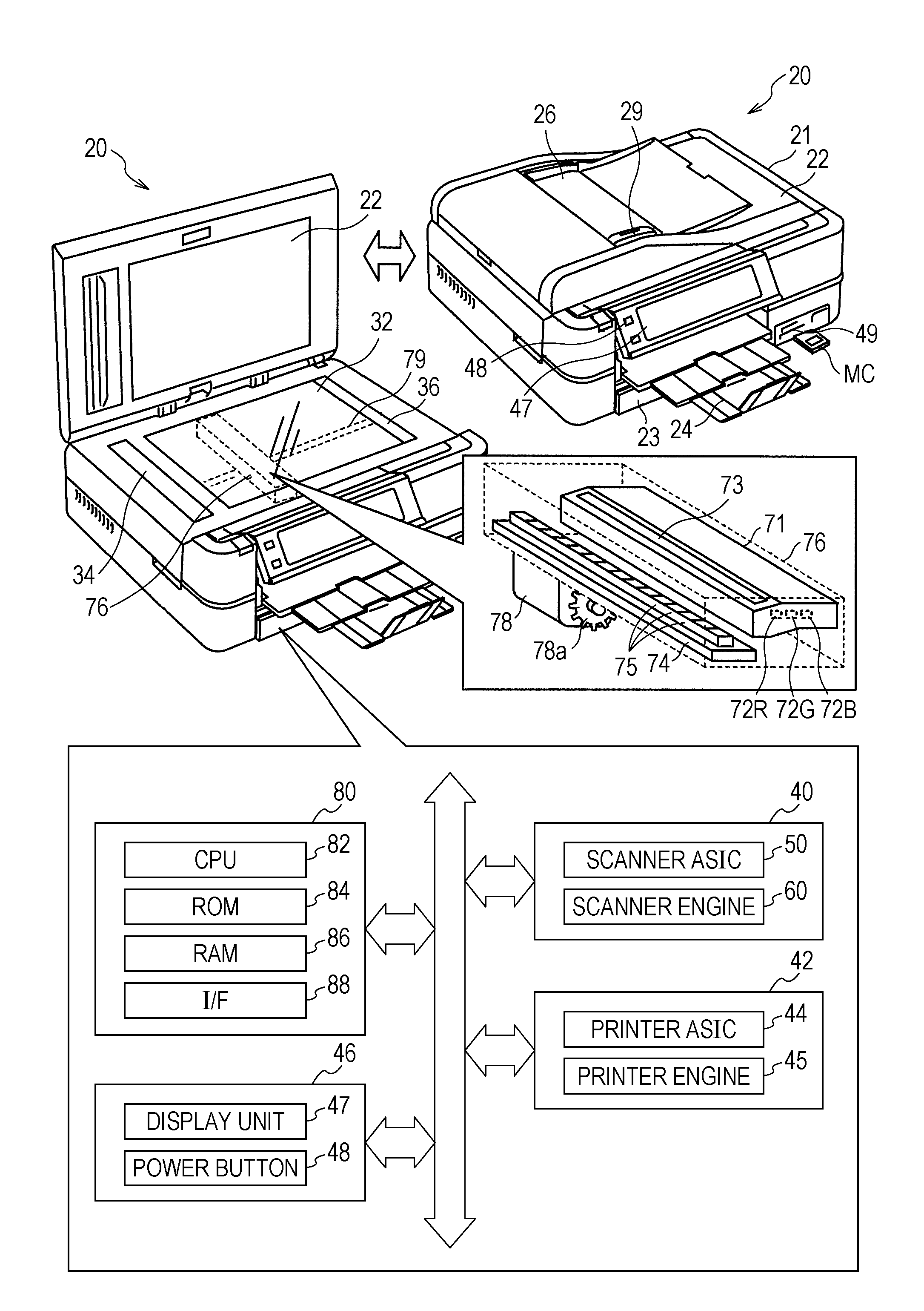
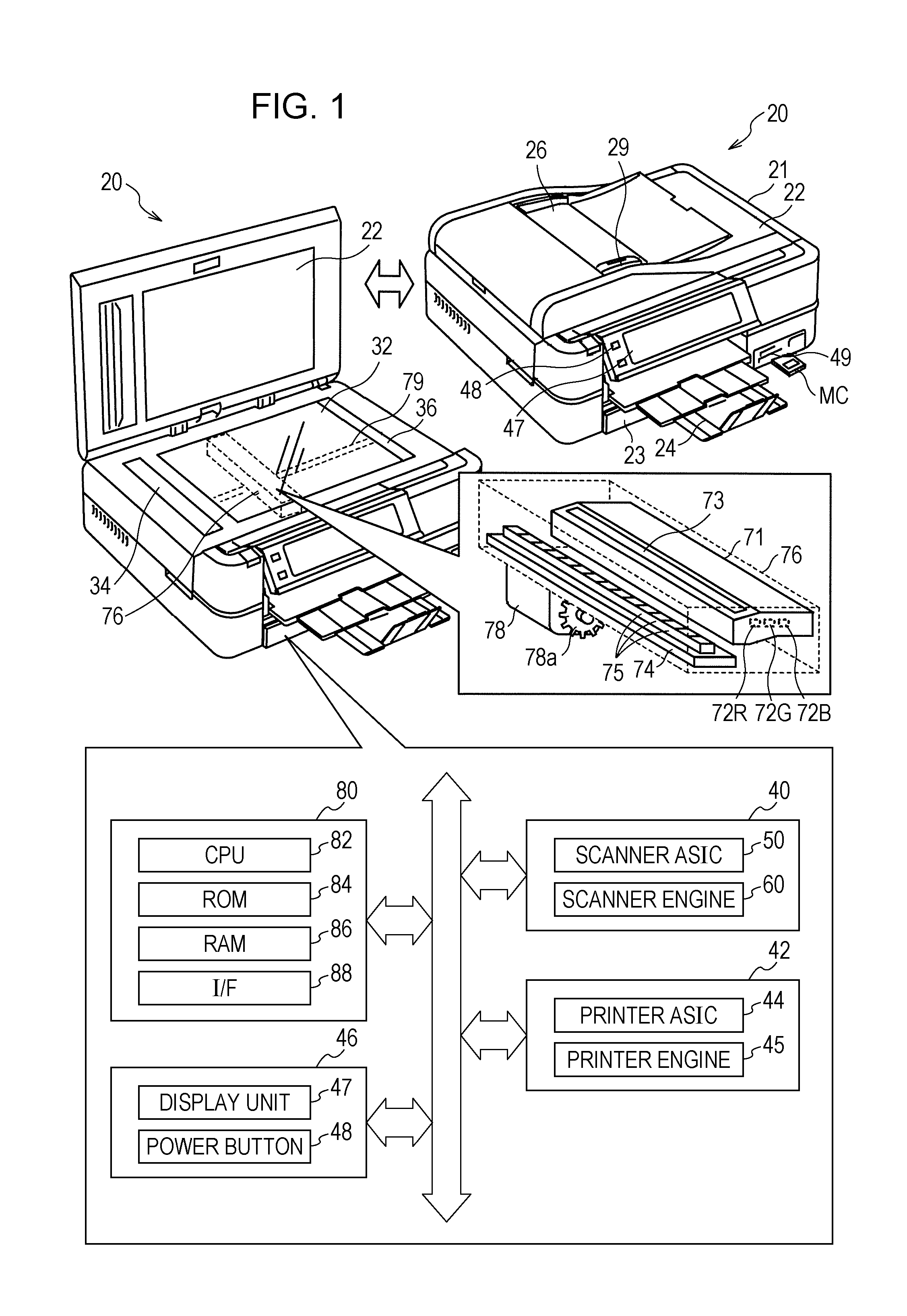
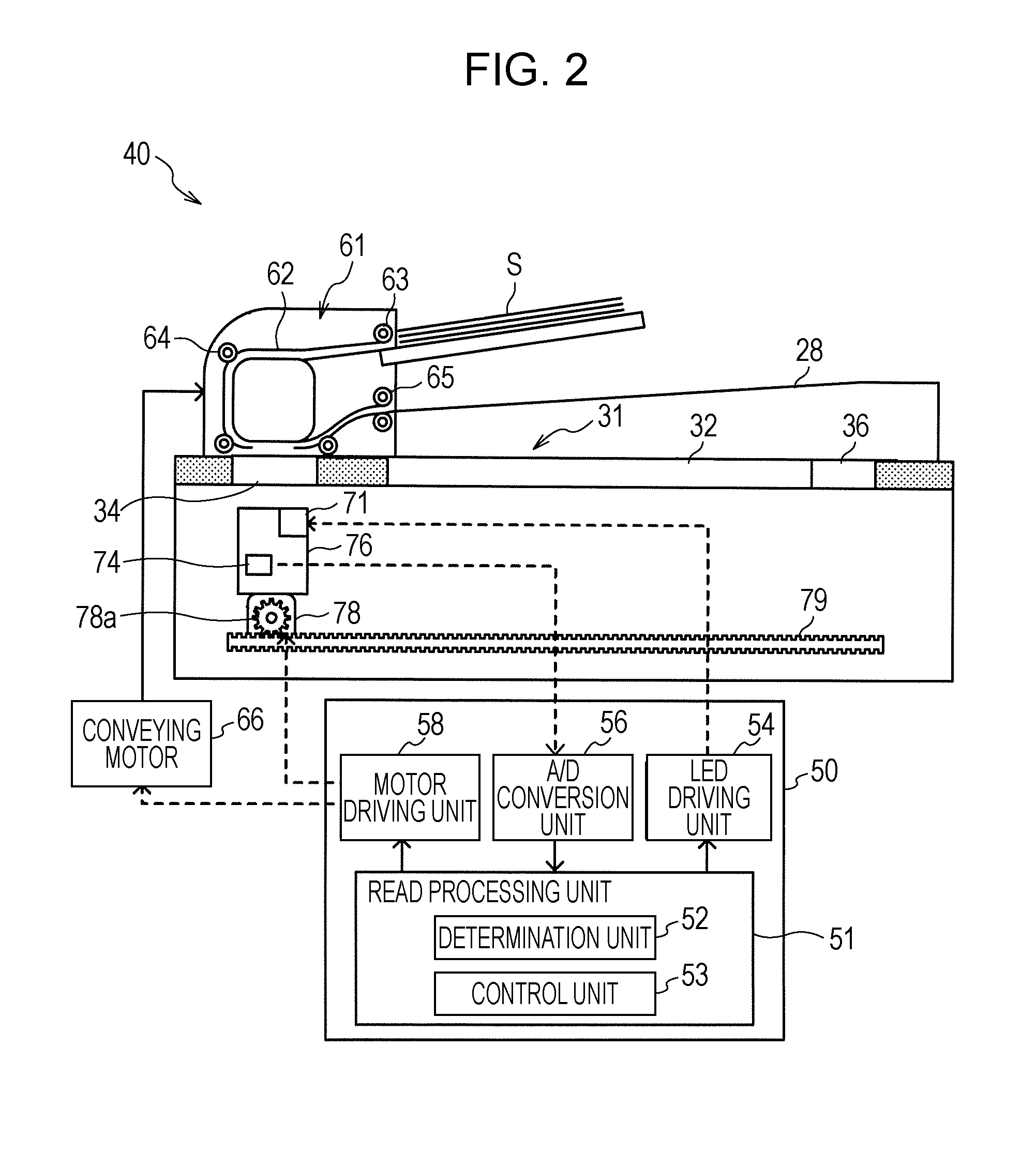
[0023]Subsequently, embodiments of the invention will be described with reference to drawings. FIG. 1 is a configuration diagram which shows a schematic configuration of a multi-function printer 20 according to an embodiment of the invention. FIG. 2 is a configuration diagram which shows a schematic configuration of a scanner unit 40.

[0024]The multi-function printer 20 according to the embodiment, as shown in FIG. 1, is formed of a housing 21, an openable and closable housing cover 22 at the top face of the housing 21, and includes a scanner unit 40 which optically reads out the original document and generates image data, a printer unit 42 which feeds and prints sheets which are set in a cassette 23 and discharges the sheets to a sheet discharge tray 24, an operation panel 46 with which a user is able to perform various operations, and a main controller 80 which is in charge of the overall control of the apparatus. On the top face of the housing 21, a flat bed portion 31 having a gl...


PUM


Abstract

A scanner unit includes, a CIS module having a light source unit, and a CIS which receives reflected light which is emitted in the light source unit; a carriage motor which is provided in the vicinity of the CIS module, and operates along with heat when reading out using the CIS module; a determination unit which determines whether or not dark period measurement data read out using the CIS module in a dark period is in a predetermined range of a reference dark period which is set corresponding to a temperature of the carriage motor; and a control unit which controls the carriage motor so as to limits an operation of the carriage motor in read processing, when the dark period measurement data is not in the range of the reference dark period.

Description

CROSS REFERENCES TO RELATED APPLICATIONS[0001]The entire disclosure of Japanese Patent Application No. 2010-275494, filed Dec. 10, 2010 is expressly incorporated by reference herein.BACKGROUND[0002]1. Technical Field[0003]The present invention relates to an image reading apparatus, a control method and program thereof.[0004]2. Related Art[0005]In the related art, as an image reading apparatus of this type, an apparatus is proposed in which a positional deviation of a lens unit with respect to a photoelectric conversion unit is detected, when the positional deviation occurs due to a difference in thermal expansion between the lens unit and the photoelectric conversion unit, correction data is selected among plural pieces of correction data which are stored in advance, on the basis of the detected deviation, and an electric signal is corrected based on the corrected data (JP-A-2010-56732). In this apparatus, the influence due to changes in temperature is reduced, the reading quality o...

Claims


Application Information

Patent Timeline
14 Jun 2012
Publication
US20120147439A1
IPC
H04N1/40
CPC
H04N1/00925; H04N1/1017; H04N2201/0081; H04N1/4076; H04N1/193
Inventors
TAKI, HIDEO