Thermal mechanical drive actuator, thermal probe and method of thermally driving a probe

a technology of mechanical drive actuator and probe, which is applied in the direction of mechanical roughness/irregularity measurement, instruments, measurement devices, etc., can solve the problems of inability to achieve the effect of reducing the number of components, inability to manufacture these types of composite cantilevers, and inability to meet the requirements of the application

Active Publication Date: 2008-01-17
BRUKER NANO INC
View PDF11 Cites 44 Cited by
  • Summary
  • Abstract
  • Description
  • Claims
  • Application Information

AI Technical Summary

Benefits of technology

[0048]According to another embodiment, the thermal stress differential between the heating element and the drive cantilever constrained at both ends changes a spring constant of the constrained cantilever without causing substantial deflection of the cantilever.

Problems solved by technology

Because AFM's use such small cantilevers, which are roughly 1000 times smaller than the cantilevers used in more traditional cantilever measurement instruments, it has been a challenge to couple the piezoelectric actuation to excite the cantilevers.
The excess mechanical energy passed to the environment often results in parasitic resonances of the entire fixture.
These problems can be tolerable in certain instances, for example when the analysis is performed in air given the high mechanical Q of the cantilever.
This is one of the major problems with AFM operation in fluid.
Unfortunately, fabrication of these types of composite cantilevers can be undesirably complicated and may not always work well in a fluid environment, particularly when passivation is required.
While this type of composite cantilever requires no passivation, the magnetic drive coil inherently functions as a low pass filter, which can undesirably limit the frequency at which it can oscillate the cantilever.
In addition, this type of composite cantilever fabrication poses considerable challenges, especially with regard to large current heating of the coil, in the order of one amp.
Finally, sharpness of the probe tip is often compromised as a result of the magnetic coating, which can significantly limit the applications in which this type of a composite cantilever can be used.
While an ultrasonic drive works with any type of cantilever and does not require any special cantilever fabrication, it poses its own unique challenges because it requires focusing of the ultrasonic waves into a beam that accurately impinges against the cantilever.
Because scanning probe cantilevers are so small, it can be difficult to consistently focus the ultrasonic beam onto the cantilever resulting in inconsistent drive operation.
In addition, where the cantilever is used in a fluid environment, the ultrasonic beam typically creates a high pressure gradient in the fluid, which can lead to a disadvantageous phenomenon called “acoustic streaming.” When this occurs, the high pressure gradient in the fluid causes fluid convection in the vicinity of the cantilever, which may cause the cantilever to move in a random and uncontrollable manner.
Cantilever force sensing can be compromised, which in turn can adversely impact cantilever control, all of which can render the results obtained unusable.

Method used


Image

  • Thermal mechanical drive actuator, thermal probe and method of thermally driving a probe
  • Thermal mechanical drive actuator, thermal probe and method of thermally driving a probe
  • Thermal mechanical drive actuator, thermal probe and method of thermally driving a probe

Examples


Embodiment Construction

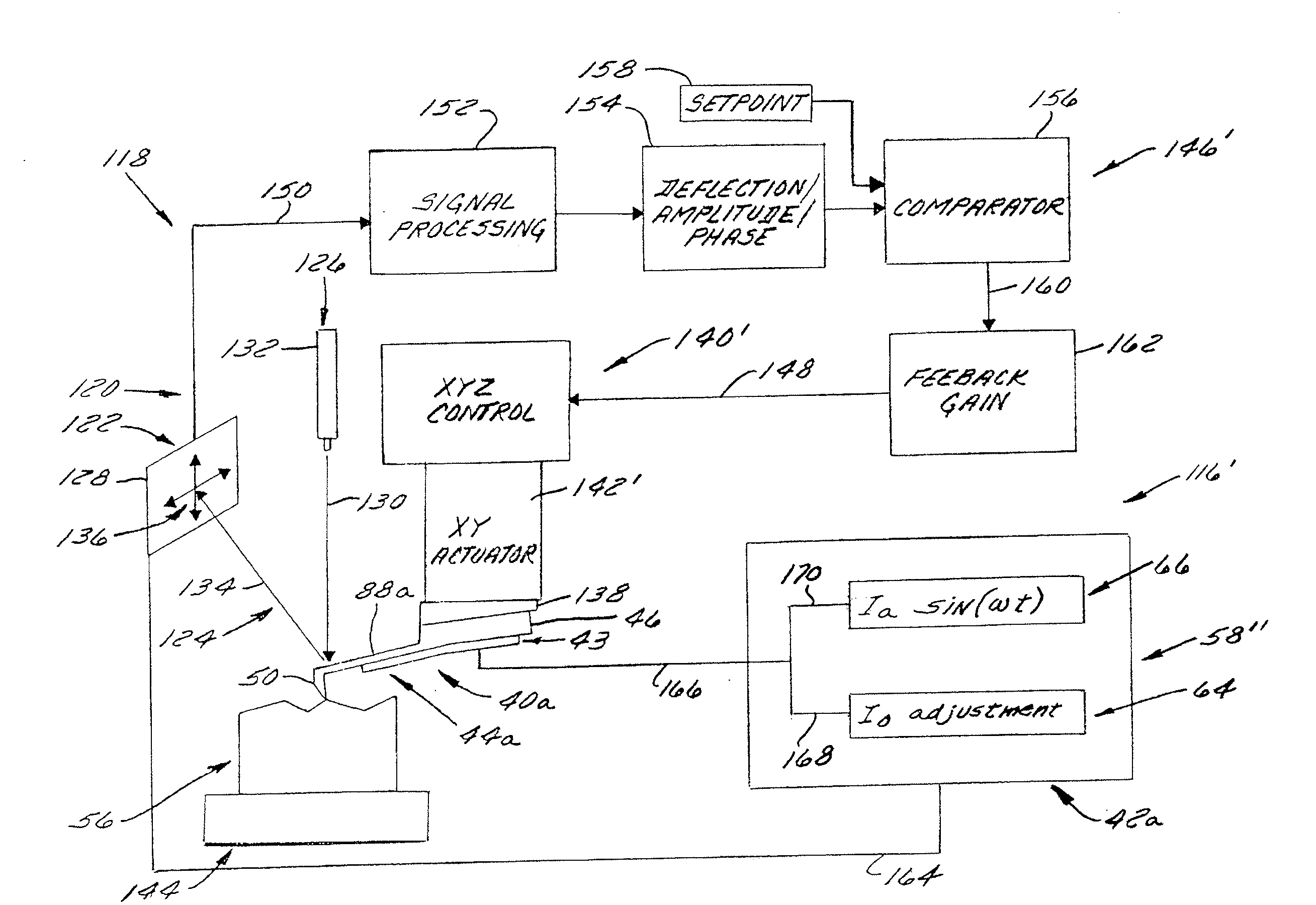
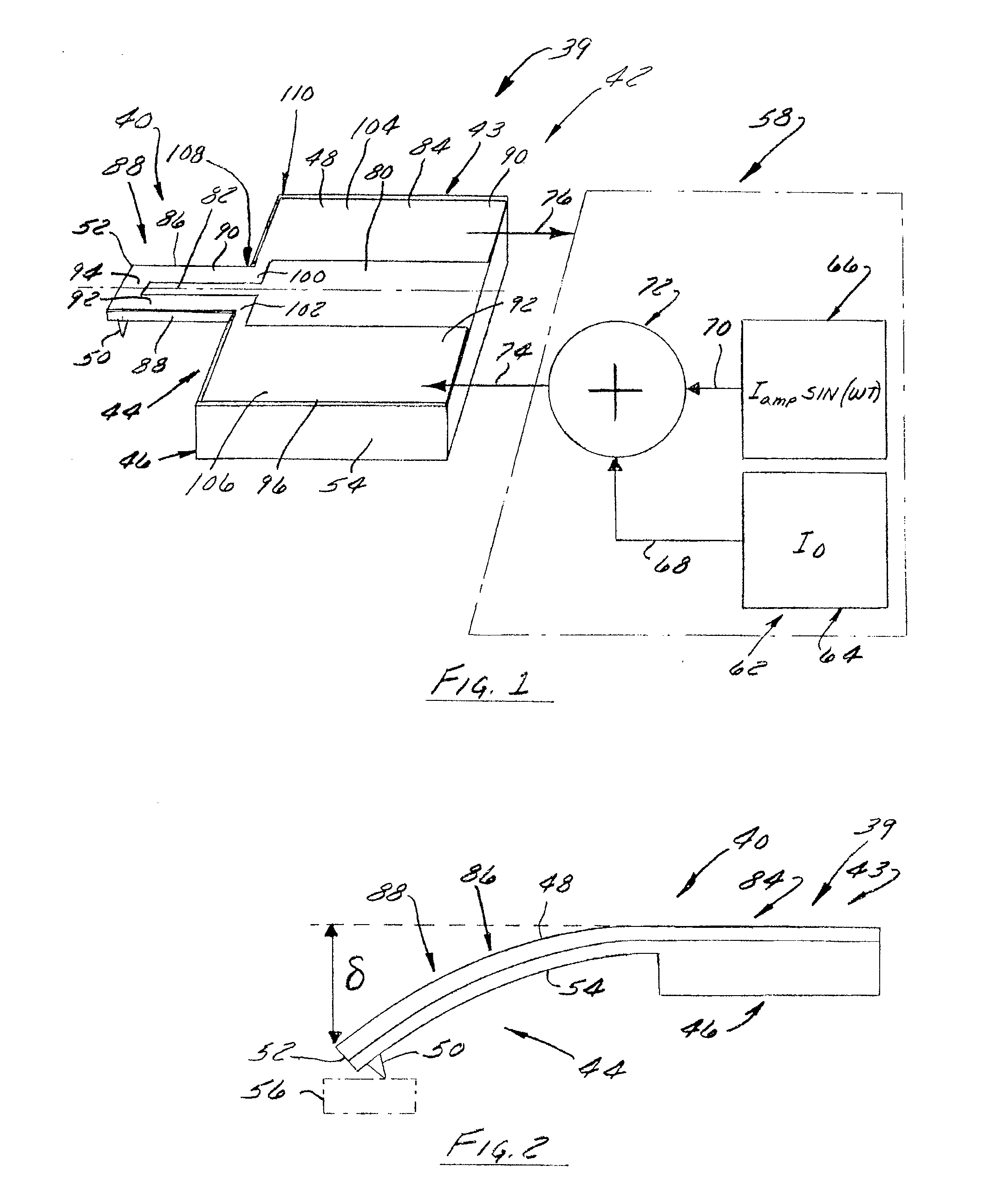
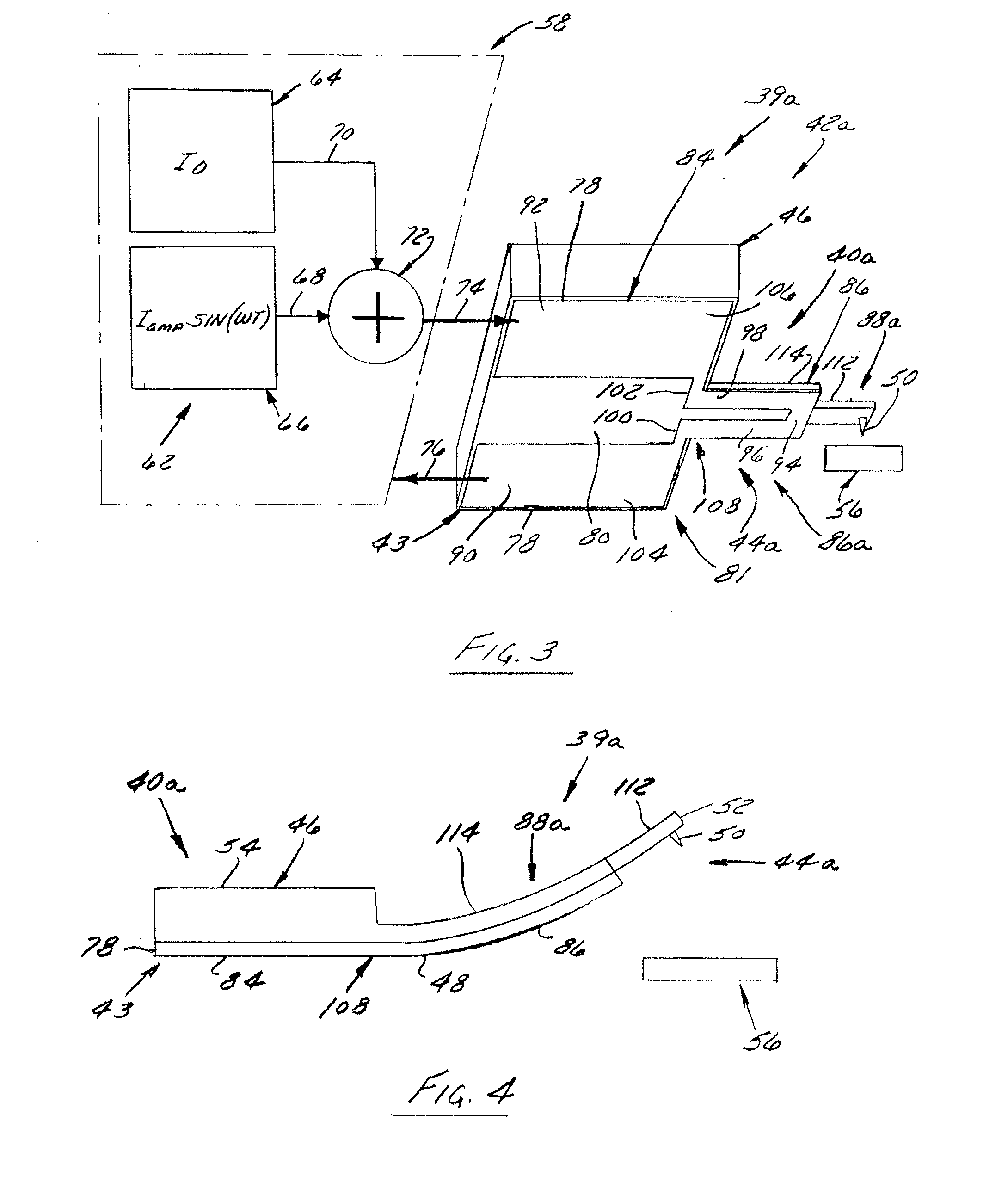
[0080]FIG. 1 illustrates a preferred and exemplary embodiment of a thermally drivable probe device 39 including a probe 40 and a thermal mechanical drive 42 that is constructed and arranged to facilitate displacement or excitation thereof. The probe 40 includes a cantilever 44 that defines a lever arm or lever 88 extending outwardly from a substrate or base 46 of probe device 39 at its fixed end. The thermal mechanical drive 42 includes a thermal actuator 43 that is disposed in thermally conductive contact with at least a portion of the cantilever 44, such as the lever 88, the substrate 46, or both the lever 88 and substrate 46 (such as depicted in FIG. 1). The thermal actuator 43 preferably is composed of a electrically and thermally conductive material 48 that facilitates thermal energy transfer to, thermal energy transfer from, or thermal energy transfer to and from the cantilever 44. Notably, the components of probe device 39 may be manufactured independently and coupled or as a...


PUM


Abstract

A drive actuator for a measurement instrument having a probe, the drive actuator including a heating element in a thermally conductive relationship with the probe such that application of electric current to the heating element modifies a characteristic of the probe. The probe device includes a probe including a cantilever having a lever made of a material having a selected thermal expansivity and a drive actuator in operable cooperation with the cantilever lever made of a material having a thermal expansivity different than the thermal expansivity of the material of which the cantilever lever is made.

Description

FIELD OF THE INVENTION[0001]The present invention is directed to an actuator to effect displacement of a cantilever of a measurement instrument, including that which is used in probe-based instruments of the type used in the field of scanning probe microscopy and the like, and more particularly, relates to a method and thermal mechanical drive apparatus for displacing a cantilever in a manner capable of providing positional control and sensing, as well as exciting a cantilever into oscillation.BACKGROUND OF THE INVENTION[0002]Several probe-based instruments have been developed that obtain information from the interaction between its sensing element and a sample being analyzed. At least some of these employ a stylus or tip carried by a lever, such as the lever of a cantilever. The stylus is located at or adjacent the free end of the cantilever and interacts with a sample during instrument operation to obtain information about the sample, such as size, surface contour or topography, s...

Claims


Application Information

Patent Timeline
Patent Type & Authority Applications(United States)
IPC IPC(8): G01B5/28
CPCG01Q10/045B82Y35/00
Inventor SU, CHANMINDANIELS, ROBERT C.PRATER, CRAIG
Owner BRUKER NANO INC
Why Eureka
Try Eureka