
Printing apparatus and printing method

a printing apparatus and printing method technology, applied in printing presses, typewriters, printing, etc., can solve the problems of lowering the printing quality, and lowering the quality of printing from the materials thus attached, and achieve the effect of the same operation

Active Publication Date: 2015-05-07
SEIKO EPSON CORP
View PDF9 Cites 23 Cited by
  • Summary
  • Abstract
  • Description
  • Claims
  • Application Information

AI Technical Summary

Benefits of technology

The invention provides a printing apparatus and printing method that can prevent poor print quality caused by attached materials on the printing surface. The removal portion of the printing apparatus removes the attached materials from the printing surface, and the pressing portion flattens the printing surface to prevent any distortion caused by the removal process. The adhesive roller with adhesive contacting the printing surface can remove the attached materials, and the peeling portion prevents the printing medium from flying off during the process. These features improve the printing quality and efficiency of the printing apparatus.

Problems solved by technology

Incidentally, in the textile printing apparatus as described above, when the ink jet head approaches the printing material and ejects ink, fluff or lint attached to the printing material comes into contact with the ink jet head, which may lead to ink ejection defects.
At this time, when attached materials, such as fluff, attached to the printing material adheres to the ink jet head, ink mist that occurs along with the ejection of ink may condense on the surface of the attached material and drops onto the printing material, thereby lowering the printing quality.
That is, there is a problem in that when fluff or the like attaches to the printing material, a lowering of the quality of printing stemming from the materials thus attached may occur.

Method used


Image

  • Printing apparatus and printing method
  • Printing apparatus and printing method
  • Printing apparatus and printing method

Examples


first embodiment

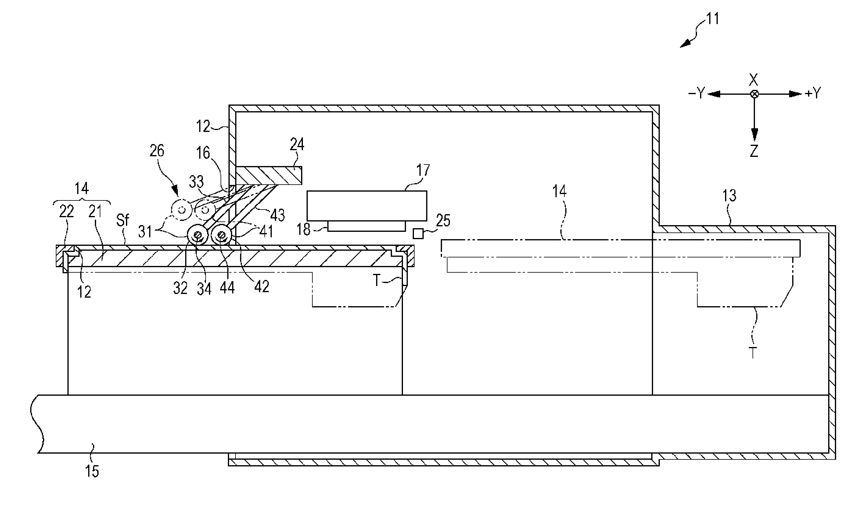
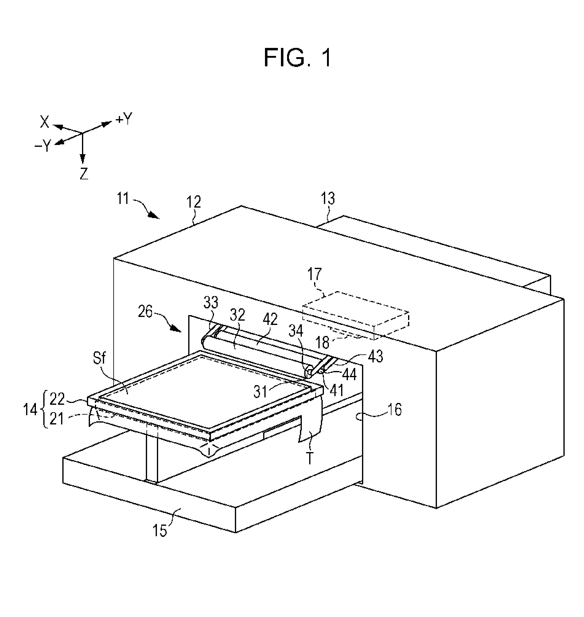
[0031]Below, a first embodiment of the printing apparatus will be described with reference to the drawings. The printing apparatus, for example, is an ink jet printer (textile printing apparatus) that performs printing through textile printing by ejecting ink that is an example of a liquid on the printing surface with the cloth surface of a fabric (T-shirt), which is an example of a printing medium, as a printing surface.

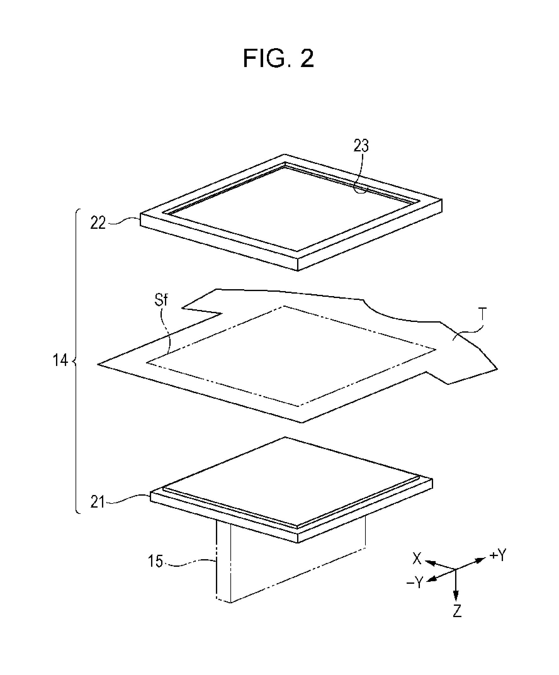
[0032]As shown in FIG. 1, the printing apparatus 11 of the embodiment includes a substantially rectangular box-like housing portion 12, an accommodation portion 13 protruding from the housing portion 12, a mounting portion 14 able to reciprocate in a state in which the printing medium T is mounted, and a transport portion 15 for the mounting portion 14 to be reciprocated.

[0033]In the present embodiment, the direction in which the accommodation portion 13 protrudes from the housing portion 12 is referred to as backward, and the direction in which the transport portio...

second embodiment

[0075]Next, the second embodiment of the printing apparatus will be described with reference to FIG. 5.

[0076]In contrast to the mounting portion 14 moving relative to housing portion 12 in the first embodiment, the printing apparatus 11A of the second embodiment differs in that the housing portion 12A moves relative to the mounting portion 14A. Since members to which the same reference numerals are applied in both embodiments include the same configuration, description thereof will not be made, and description will be provided below focusing on the points of difference from the first embodiment.

[0077]As shown in FIG. 5, the housing portion 12A of the printing apparatus 11A holds the carriage 17 on which the liquid ejecting portion 18 is mounted and the processing mechanism 26A, and reciprocally moves along the movement direction Y (+Y, −Y) with respect to the mounting portion 14A on which the printing medium T is mounted. The movement direction +Y is the right direction in FIG. 5, a...

third embodiment

[0096]Next, a third embodiment of the printing apparatus will be described with reference to FIG. 6.

[0097]The printing apparatus of the third embodiment differs from the first embodiment in that the liquid ejecting portion performs the printing process and the processing mechanism that is not moving performs surface processing with respect to the printing surface of the printing medium transported in the transport direction. Since members to which the same reference numerals are applied in both embodiments include the same configuration, description thereof will not be made, and description will be provided below focusing on the points of difference from the first embodiment.

[0098]As shown in FIG. 6, the printing apparatus 11B includes a housing portion 12B that holds a carriage 17, a transport mechanism 45 that transports the long printing medium T in the transport direction F, and a processing mechanism 26B arranged further to the upstream side in the transport direction F than th...


PUM


Abstract

A printing apparatus includes a removal portion that removes attached materials attached to a printing surface by coming in contact with the printing surface of a printing medium; a pressing portion that presses the printing surface with which the removal portion is in contact; and a liquid ejecting portion that performs printing by ejecting a liquid with respect to the printing surface pressed by the pressing portion.

Description

BACKGROUND[0001]1. Technical Field[0002]The present invention relates to a printing apparatus, such as a printer, and a printing method.[0003]2. Related Art[0004]One example of a printing apparatus is an ink jet textile printing apparatus that performs printing of a T-shirt by ejecting ink on a T-shirt that is a material to be printed from an ink jet head that is a printing execution portion, thereby printing a design (for example, JP-A-2013-19083).[0005]Incidentally, in the textile printing apparatus as described above, when the ink jet head approaches the printing material and ejects ink, fluff or lint attached to the printing material comes into contact with the ink jet head, which may lead to ink ejection defects. At this time, when attached materials, such as fluff, attached to the printing material adheres to the ink jet head, ink mist that occurs along with the ejection of ink may condense on the surface of the attached material and drops onto the printing material, thereby l...

Claims


Application Information

Patent Timeline
Patent Type & Authority Applications(United States)
IPC IPC(8): B41J11/00B41F17/38
CPCB41F17/38B41J11/0015B41J3/4078
Inventor SHINODA, TOMOKIFUJIOKA, KAZUYUKIMATSUMOTO, KEIJI
Owner SEIKO EPSON CORP
Learn More