
Image-capturing apparatus

a technology of image-capturing apparatus and af control, which is applied in the direction of exposure control, printers, camera focusing arrangement, etc., can solve the problems of high-accuracy af and high-accuracy control, and achieve high accuracy, suppress a decrease in continuous capture speed, and high accuracy

Inactive Publication Date: 2009-06-11
SONY CORP
View PDF21 Cites 33 Cited by
  • Summary
  • Abstract
  • Description
  • Claims
  • Application Information

AI Technical Summary

Benefits of technology

[0010]It is desirable to provide an image-capturing apparatus capable of performing phase-difference AF with high accuracy while suppressing a decrease in a continuous capturing speed.
[0013]According to the embodiments of the present invention, in continuous image capturing in which image-capturing elements having a focus detection pixel sequence in which two or more pairs of pixels that receive light fluxes of object light that has been transmitted through a pair of partial areas in an exit pupil of an image-capturing optical system are arranged along a predetermined direction are sequentially actually exposed, focus adjustment is performed between actual exposures on the basis of a result of focus detection of a phase-difference detection method based on a predetermined signal generated by a focus detection pixel sequence by an actual exposure and a result of focus detection of a phase-difference detection method based on a specific signal generated by a pair of line sensors by another exposure to the sensor unit, which is performed during intervals between actual exposures. As a result, it is possible to perform phase-difference AF during continuous image capturing with high accuracy while suppressing a decrease in a continuous capturing speed.
[0014]According to the embodiments of the present invention, in continuous image capturing in which image-capturing elements having a focus detection pixel sequence in which two or more pairs of pixels that receive light fluxes of object light that has been transmitted through a pair of partial areas in an exit pupil of an image-capturing optical system are arranged along a predetermined direction are sequentially actually exposed, focus adjustment is performed between actual exposures on the basis of a result of focus detection of a phase-difference detection method based on a first signal generated by a focus detection pixel sequence by an actual exposure and a result of focus detection of a phase-difference detection method based on a second signal generated by a focus detection pixel sequence by another exposure, which is performed during intervals between actual exposures. As a result, it is possible to perform phase-difference AF during continuous image capturing with high accuracy while suppressing a decrease in a continuous capturing speed.

Problems solved by technology

However, with such phase-difference detection being performed only once, AF control with high accuracy is difficult.
In such an operation during continuous capturing, the exposure Pa of the AF module and the computation process Ma of phase-difference AF are performed only once, and therefore, high-accuracy AF is difficult.

Method used


Image

  • Image-capturing apparatus
  • Image-capturing apparatus
  • Image-capturing apparatus

Examples


first embodiment

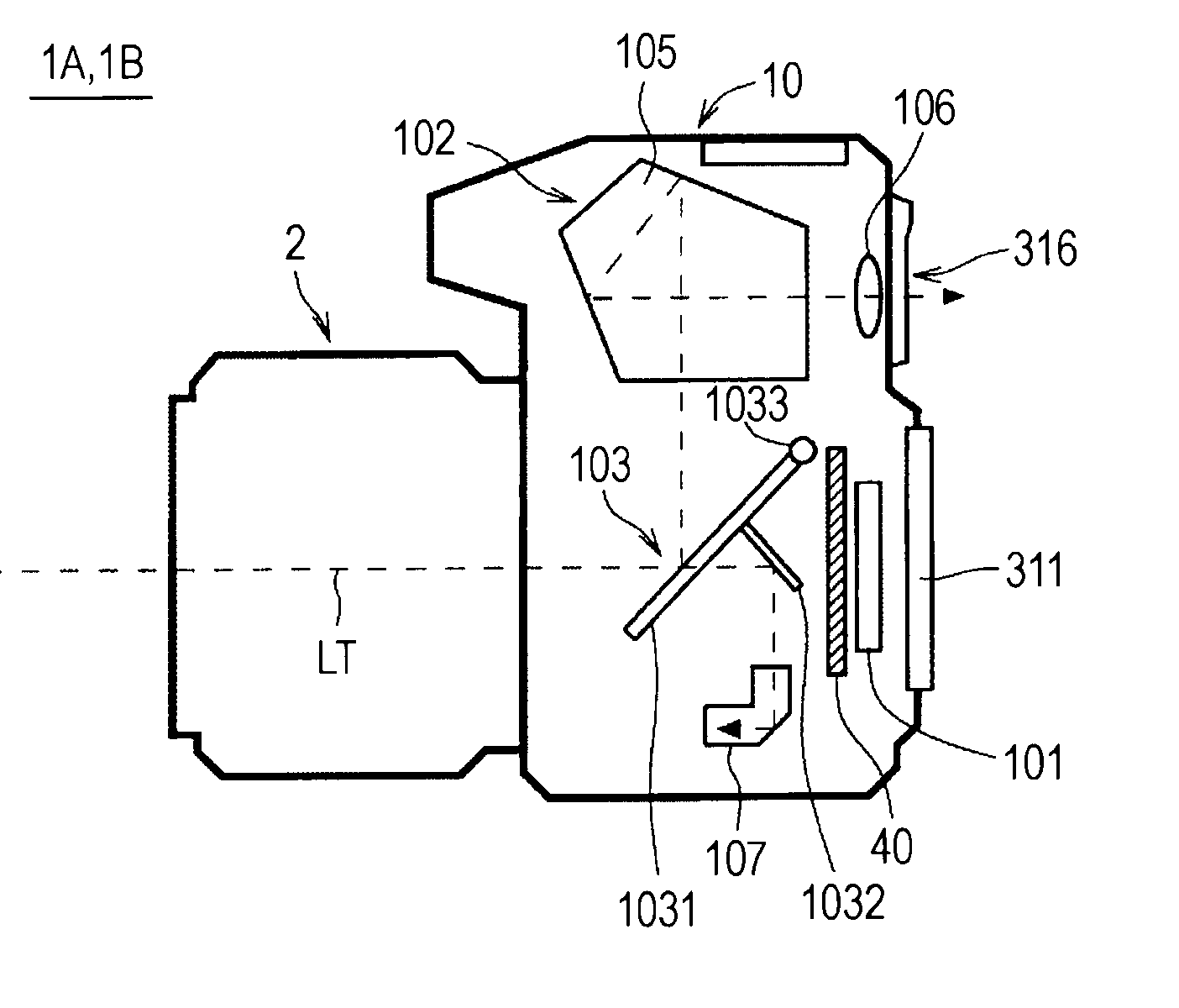
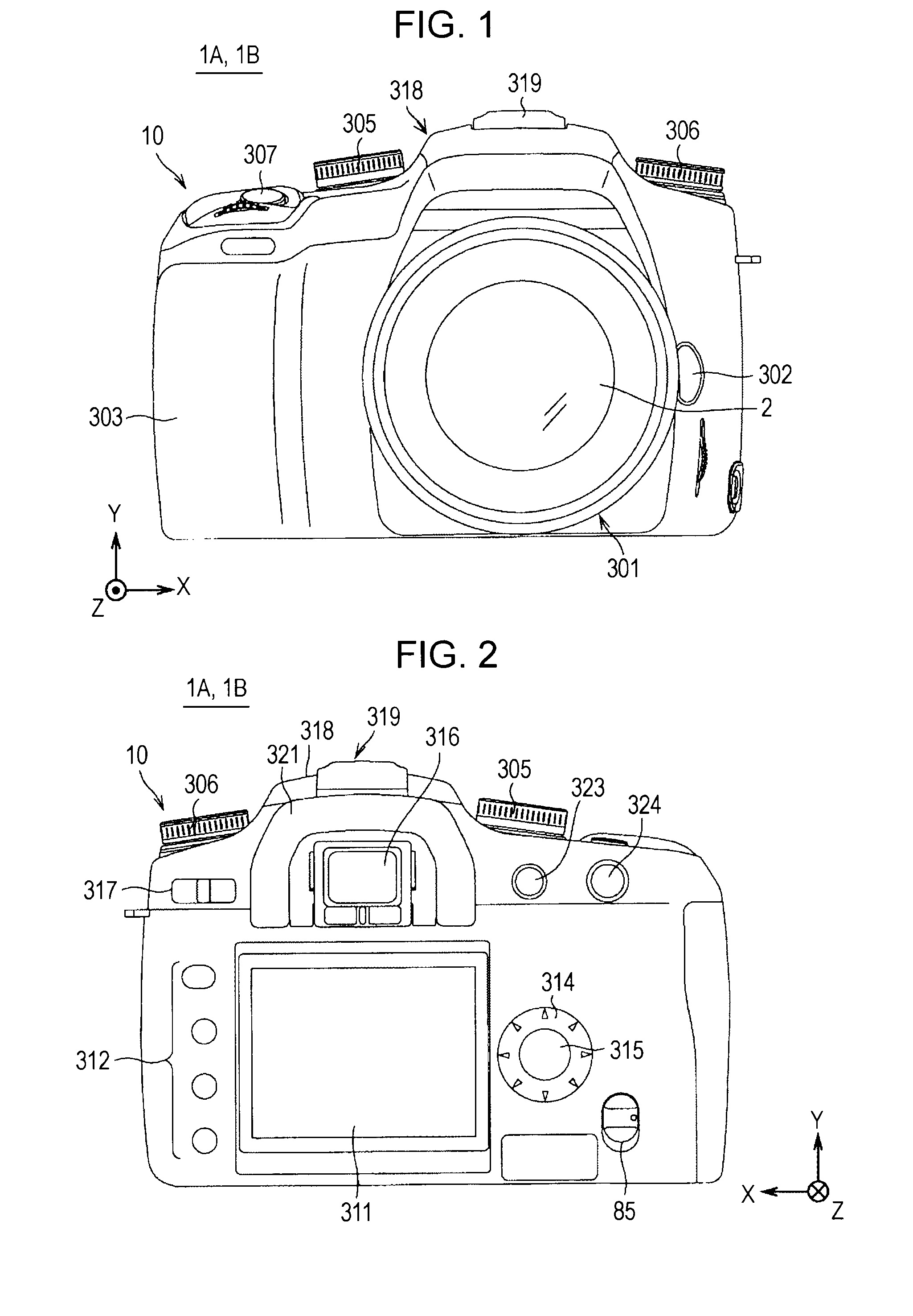
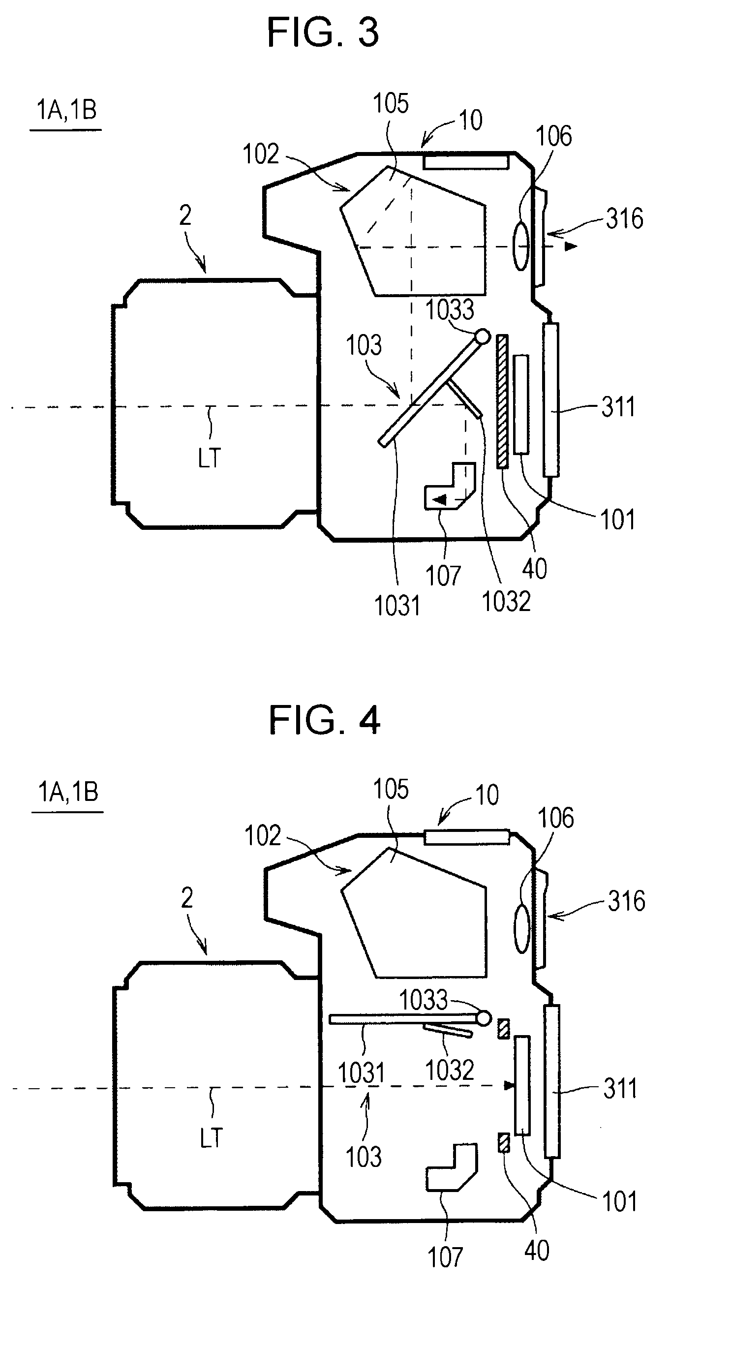
Exterior Configuration of Image-Capturing Apparatus 1A

[0033]FIGS. 1 and 2 show the exterior configuration of an image-capturing apparatus 1A according to a first embodiment of the present invention. Here, FIGS. 1 and 2 show a front view and a back view, respectively.

[0034]The image-capturing apparatus 1A is configured as, for example, a single-lens reflex digital still camera, and includes a camera body 10, and an interchangeable lens 2 serving as an image-capturing lens that can be attached to and detached from the camera body 10.

[0035]In FIG. 1, provided on the front side of the camera body 10 are a mount unit 301 in which the interchangeable lens 2 is mounted in substantially the center of the front; a lens release button 302 arranged to the right of the mount unit 301; a grip unit 303 with which gripping is possible; a mode setting dial 305 arranged in the upper left area of the front; a control value setting dial 306 arranged in the upper right area of the front; and a shutter ...

second embodiment

[0147]An image-capturing apparatus 1B according to a second embodiment of the present invention has a configuration similar to that of the image-capturing apparatus 1A of the first embodiment shown in FIGS. 1 to 5, but the configuration of the central controller differs.

[0148]That is, a central controller 62B of the image-capturing apparatus 1B has stored therein control programs for performing AF operations at the time of continuous image capturing to be described next.

AF Operation during Continuous Image Capturing

[0149]FIG. 15 is a timing chart illustrating an AF operation at the time of continuous image capturing in the image-capturing apparatus 1B.

[0150]Also, in the image-capturing apparatus 1B, similarly to the above-described image-capturing apparatus 1A, phase-difference AF based on exposure data (actual exposure data) of the image-capturing element 101 that is actually exposed in the continuous image capturing can be performed. However, whereas in the image-capturing apparat...


PUM


Abstract

An image-capturing apparatus includes an image-capturing optical system; a sensor unit having line sensors that receive light fluxes of an object, which have been transmitted through a pair of partial areas in an exit pupil of the image-capturing optical system; image-capturing elements having a pixel arrangement capable of generating an image signal and a focus detection pixel sequence, in which two or more pairs of pixels that receive the light fluxes of an object, are arranged in a predetermined direction; a continuous image-capturing unit configured to perform continuous image capturing of actually exposing the image-capturing elements; a signal generation unit configured to perform another exposure for the sensor unit; a first focus detection unit configured to perform focus detection of a phase-difference detection method; a second focus detection unit configured to perform focus detection; and a focus adjustment unit configured to perform focus adjustment.

Description

CROSS REFERENCES TO RELATED APPLICATIONS[0001]The present invention contains subject matter related to Japanese Patent Application JP 2007-318063 filed in the Japanese Patent Office on Dec. 10, 2007, the entire contents of which are incorporated herein by reference.BACKGROUND OF THE INVENTION[0002]1. Field of the Invention[0003]The present invention relates to an image-capturing apparatus having an image-capturing optical system.[0004]2. Description of the Related Art[0005]A single-lens reflex camera (image-capturing apparatus) is configured to have a mirror unit including a main mirror and a sub-mirror that can be driven so that when the mirror unit is tilted down, object light that has been transmitted through an image-capturing lens is guided to an auto-focus (AF) module (phase-difference AF module) of a phase-difference detection method and an optical finder and also, when the mirror unit is tilted up, object light is guided to an image-capturing plane.[0006]In continuous image ...

Claims


Application Information

Patent Timeline
IPC IPC(8): G03B13/32
CPCG03B13/32H04N23/672H04N23/63H04N25/704H04N25/77H04N25/134
Inventor FUJII, SHINICHIAKAMATSU, NORIHIKO
Owner SONY CORP
Learn More