

Electrode body
- Summary
- Abstract
- Description
- Claims
- Application Information
AI Technical Summary
Benefits of technology
Problems solved by technology
Method used
Image

Examples
Embodiment Construction
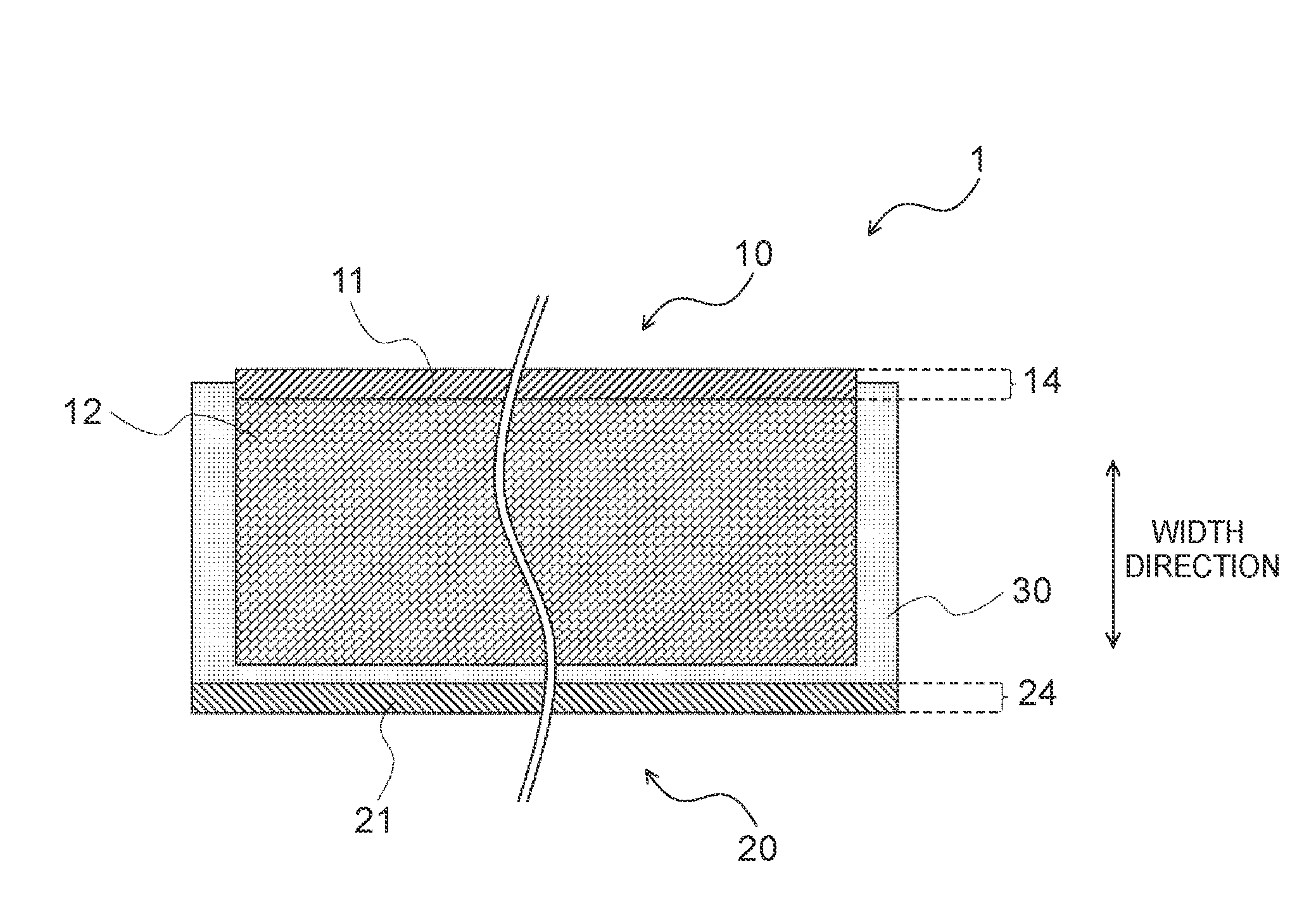
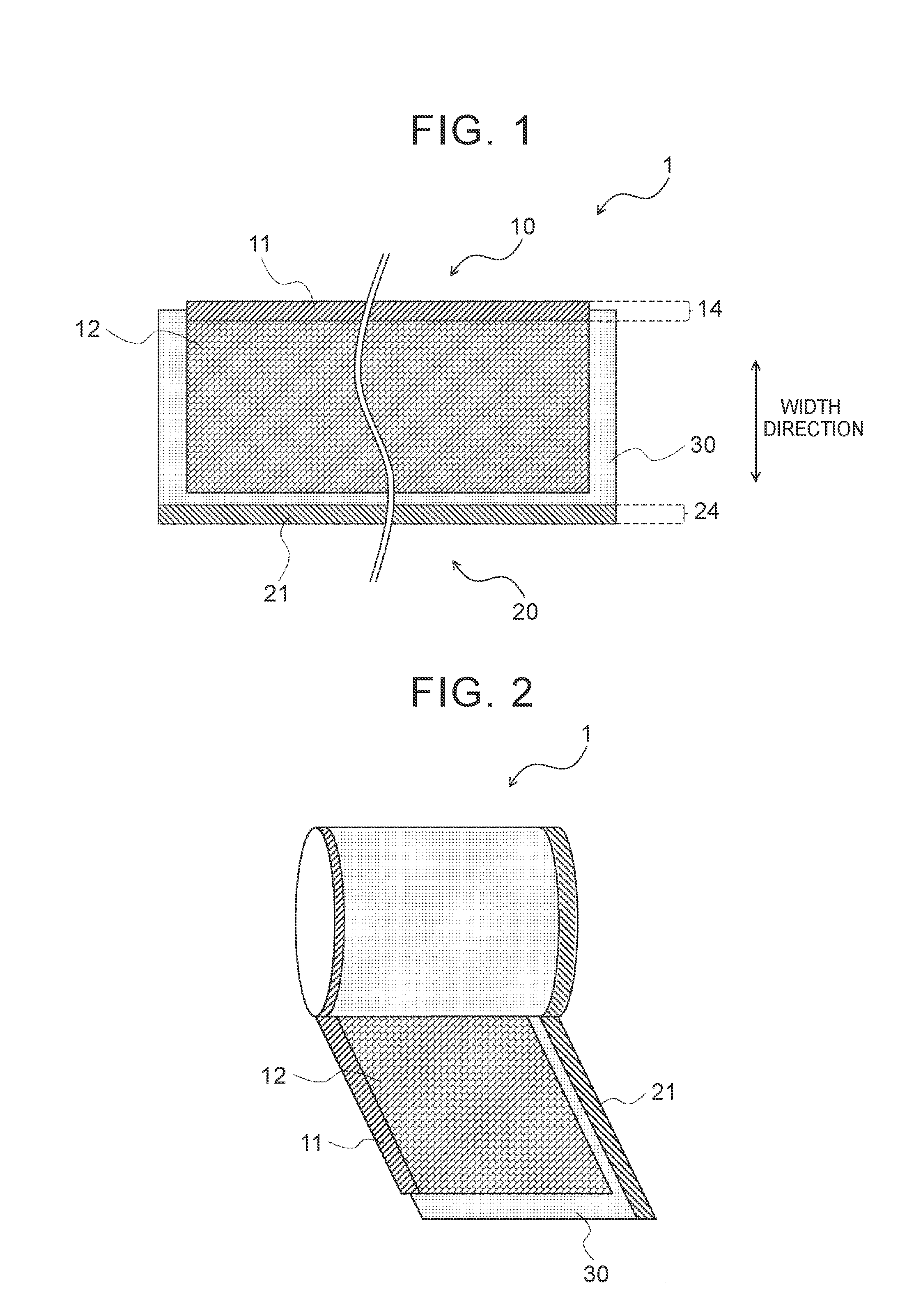
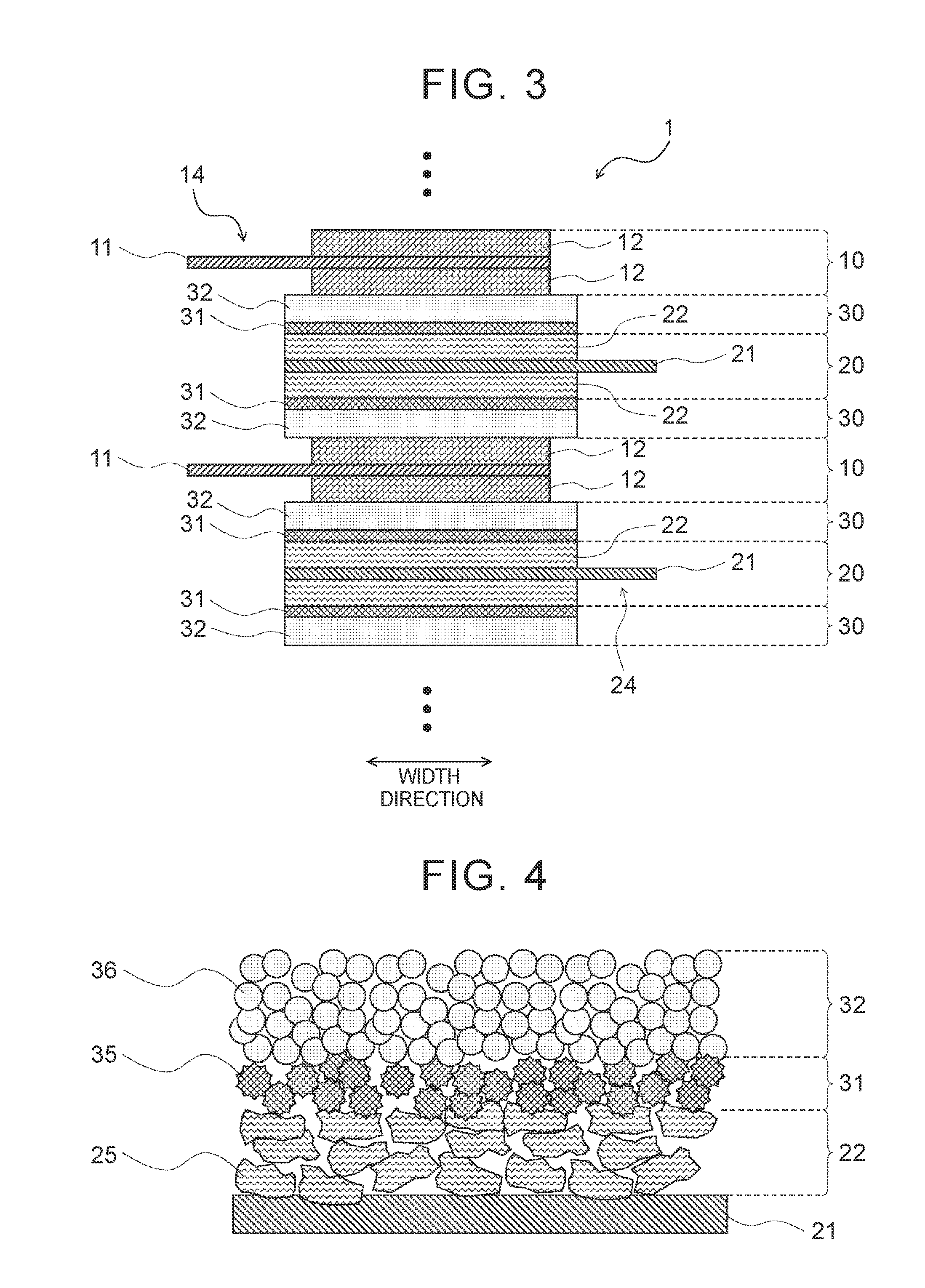
[0023]Hereinafter, an embodiment of the invention will be described with reference to the drawings. FIGS. 1 and 2 are a top view and a perspective view showing an electrode body 1 according to an embodiment of the invention, respectively. FIG. 1 shows a state of a positive electrode (positive electrode sheet) 10 and a negative electrode (negative electrode sheet) 20 before the electrode body 1 is wound. FIG. 2 shows a state where the electrode body 1 shown in FIG. 1 is being wound. FIG. 3 is a sectional view showing the electrode body 1 according to the embodiment, which is a sectional view in a laminating direction of the wound electrode body 1 shown in FIG. 2 (that is, a direction moving from a winding axis to an outer periphery of the wound electrode body 1).
[0024]As shown in FIGS. 1 to 3, the electrode body 1 according to the embodiment includes a belt-shaped positive electrode sheet 10 and a belt-shaped negative electrode sheet 20. An insulating layer 30 is arranged (formed by ...
PUM
| Property | Measurement | Unit |
|---|---|---|
| Thickness | aaaaa | aaaaa |
| Thickness | aaaaa | aaaaa |
| Thickness | aaaaa | aaaaa |
Abstract
Description
Claims
Application Information