
Electric power circuit for driving display panel

Inactive Publication Date: 2008-01-24
LAPIS SEMICON CO LTD
View PDF1 Cites 2 Cited by
  • Summary
  • Abstract
  • Description
  • Claims
  • Application Information

AI Technical Summary

Benefits of technology

[0026]It is an object of the present invention to provide a electric power circuit for driving a display panel, which can suppress a variation in voltage level of a gradation voltage, so as to generate an appropriate gradation voltage to a driver part of a display panel even if the gradation voltage is influenced by an external load.
[0028]The fine-controlling circuit fine-controls the gradation voltage in response to a difference between said gradation voltage and said referential voltage, thus suppressing excess increase and decrease of the gradation voltage so that a well-stable gradation voltage is generated.

Problems solved by technology

Since an allowable variation width for appropriately driving a typical liquid crystal panel is about ±tens mV, the variation of the gradation voltage generated by the conventional electric power circuit is too high to appropriately drive the typical liquid crystal panel, thus causing defective errors in the liquid crystal panel.
Electric current consumption in the push-pull op-amp, however, is large even at a steady state, and thus an electric power circuit having the push-pull op-amp is not usable for a mobile device.

Method used


Image

  • Electric power circuit for driving display panel
  • Electric power circuit for driving display panel
  • Electric power circuit for driving display panel

Examples


first embodiment

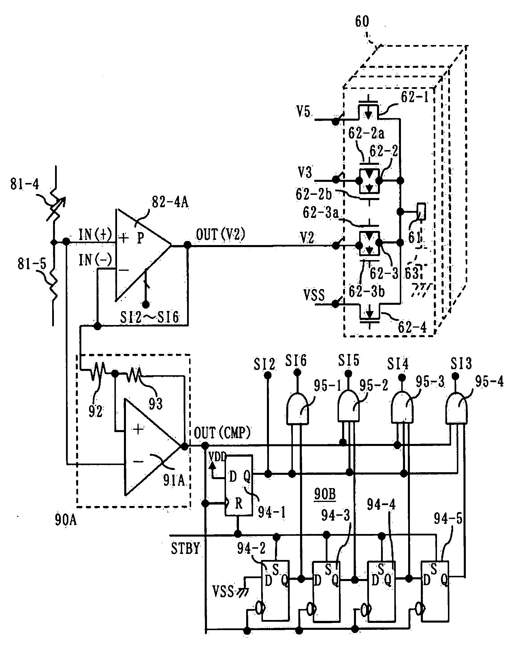
[0041]A first embodiment of the electric power circuit for driving a display panel according to the present invention will now be described with reference to FIG. 6 to 8. FIG. 6 is a block diagram showing a first embodiment of the electric power circuit for driving a display panel according to the present invention. In FIG. 6, a driver IC having one hundred EG driver parts 60 and one hundred COM driver parts 70 and an electric power circuit 80 for supplying a plurality of gradation voltages to each of the SEG and COM driver parts 60, 70 are illustrated.

[0042]Each of the SEG driver part 60 has four switches and a SEG terminal 61 connected to the four switches. The four switches, which are connected in parallel to each other, selectively supply gradation voltages generated by the electric power circuit 80 to the SEG terminal 61. The four switches are configured by a PMOS 62-1, an analogue switch 62-2 having a PMOS 62-2a and an NMOS 62-2b, an analogue switch 62-3 having a PMOS 62-3a an...

second embodiment

[0071]A second embodiment of the electric power circuit for driving a display panel according to the present invention is described with reference to FIGS. 9 to 11. In similar to the first embodiment, the second embodiment is configured by a reference voltage generation circuit having six resistors and five operational amplifiers. The reference voltage generation circuit is connected across VDD and VSS terminals, to which a voltage of VDD and an earth voltage VSS are supplied respectively. Intermediate voltages across two adjacent resistors among the six resistors are respectively connected to the five operational amplifiers. The second embodiment supplies gradation voltages to a driver IC including one hundred SEG driver parts 60 and one hundred COM driver parts 70 so as to drive a STN liquid display panel. FIG. 9 is a schematic circuit diagram showing a main part of the second embodiment of the electric power circuit for driving a display panel. FIG. 10 is a schematic circuit diag...


PUM


Abstract

An electric power circuit for driving a display panel, which supplies a plurality of gradation voltages to driver parts of the display panel, is provided. The electric power circuit has a fine-controlling circuit for fine-controlling the gradation voltage in response to a difference between the gradation voltage and a referential voltage, by which excess increase and decrease of the gradation voltage can be appropriately suppressed. Therefore, the electric power circuit can generates a stable gradation voltage.

Description

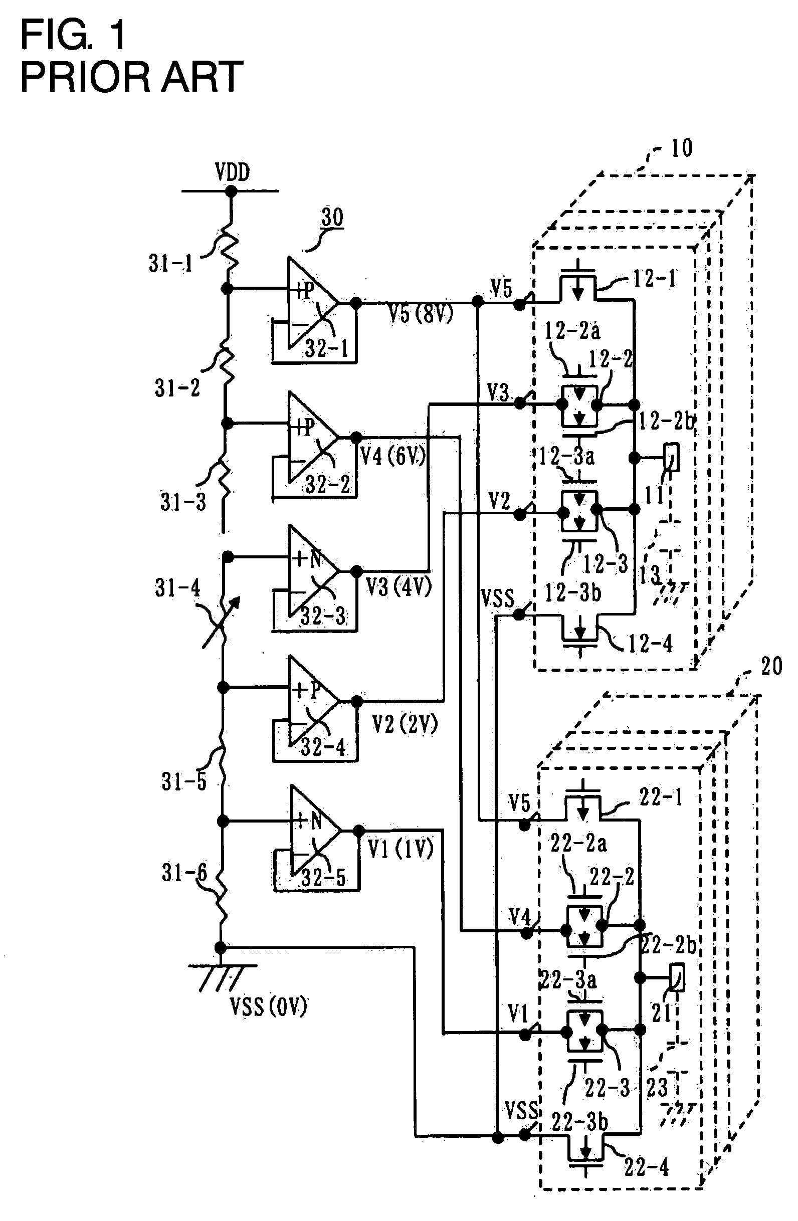
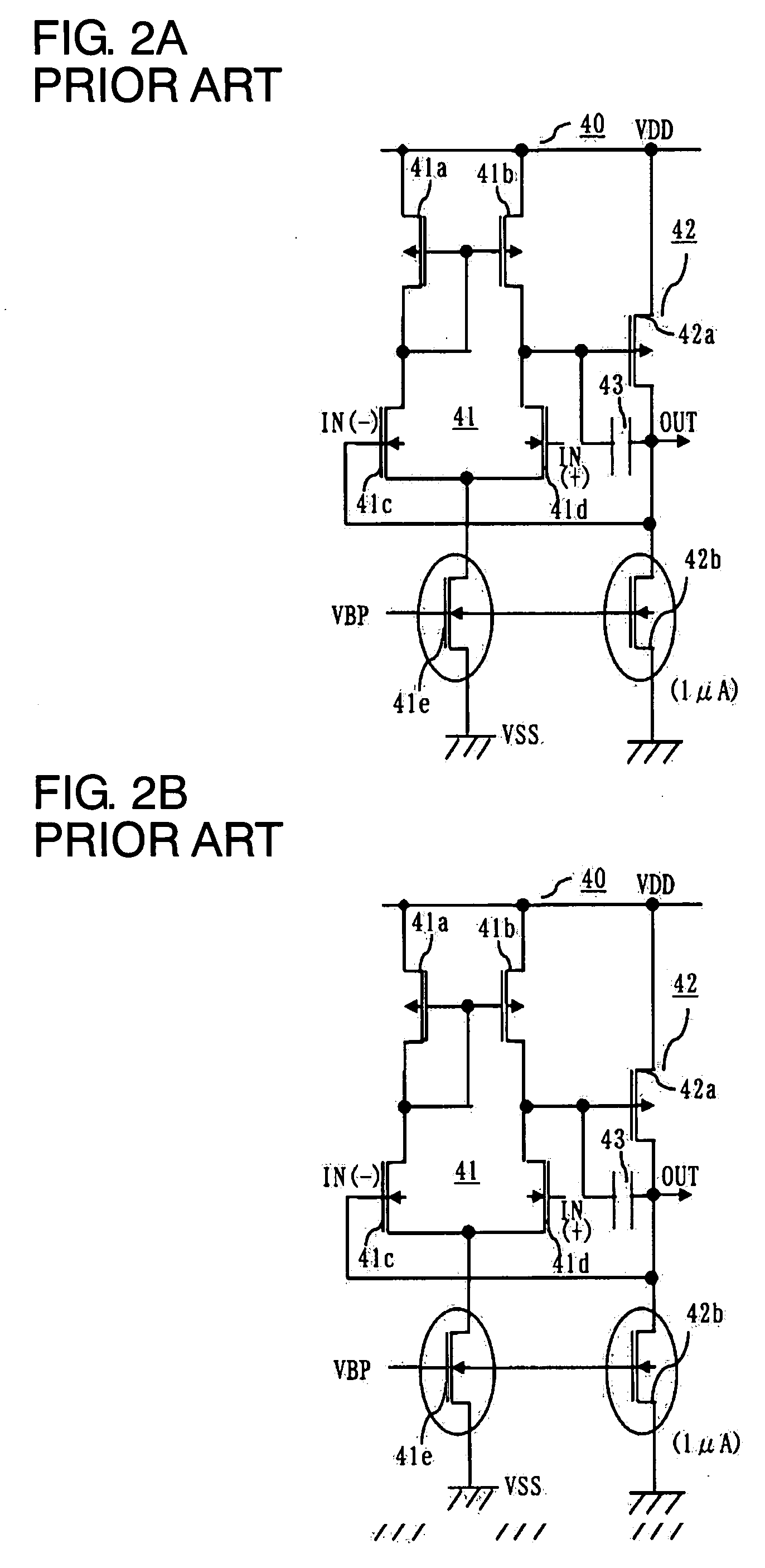
BACKGROUND OF THE INVENTION[0001]1. Field of the Invention[0002]The present invention relates to an electric power circuit, and in particular, relates to an electric power circuit for driving a display panel, which circuit supplies a plurality of gradation voltages to driver parts of the liquid crystal panel.[0003]2. Description of the Related Art[0004]A conventional driver integrated circuit (IC) for driving a STN (Super Twisted Nematic) liquid crystal panel is configured by a plurality of segment (SEG) driver parts and a plurality of common (COM) driver parts. Each of the SEG driver parts has a SEG terminal via which a signal voltage is applied to a liquid crystal element. Each of the COM driver parts has a COM terminal via which a scanning voltage is applied to a liquid crystal element. The driver IC is connected to an electric power circuit for supplying gradation voltages to the plurality of the COM and SEG driver parts. A conventional electric power circuit is described in, fo...

Claims


Application Information

Patent Timeline
IPC IPC(8): G05F1/10G06G7/12
CPCG09G3/3696
Inventor URESHINO, YOSHIMICHI
Owner LAPIS SEMICON CO LTD
Learn More