Optical module package and optical module

a technology of optical modules and optical modules, applied in the field of optical modules, can solve the problems of thermal load generation, complex work in assembling these members, and reducing the efficiency of optical coupling, and achieve the effect of improving the dimming-proof property of the optical devi

Inactive Publication Date: 2009-06-16
SEIKO EPSON CORP
View PDF8 Cites 35 Cited by
  • Summary
  • Abstract
  • Description
  • Claims
  • Application Information

AI Technical Summary

Benefits of technology

[0010]In accordance with an advantage of some aspects of the present invention, it is possible to provide an optical module that facilitates its assembling work through providing a package itself with a lens function, and is capable of suppressing a reduction in the optical coupling efficiency that may be caused by positional misalignment among composing parts. Also, it is possible to provide an optical module that can broaden the range of selection of package materials. Further, by broadening the range of selection of package materials, it is possible to provide a higher performance optical module.

Problems solved by technology

However, in the optical module described above, the optical fiber connector, the clamp and the package are composed as separate and independent members, such that the work in assembling these members is complex.
Also, when an external force (such as, a force to pull up) is applied to the optical fibers, positions between the optical fiber connector, the clamp and the package would likely be shifted from one another, which may lower the optical coupling efficiency.
Furthermore, when the optical module is bonded to a circuit substrate with solder, thermal load is generated.
When the thermal load exceeds the Tg (glass-transition temperature) of the resin, deformation of the resin poses a problem.

Method used


Image

  • Optical module package and optical module
  • Optical module package and optical module
  • Optical module package and optical module

Examples


Embodiment Construction

[0034]Preferred embodiments of the invention are described below with reference to the accompanying drawings. It is noted that members having the same functions shall be appended with the same or related reference numbers, and their descriptions shall not be repeated.

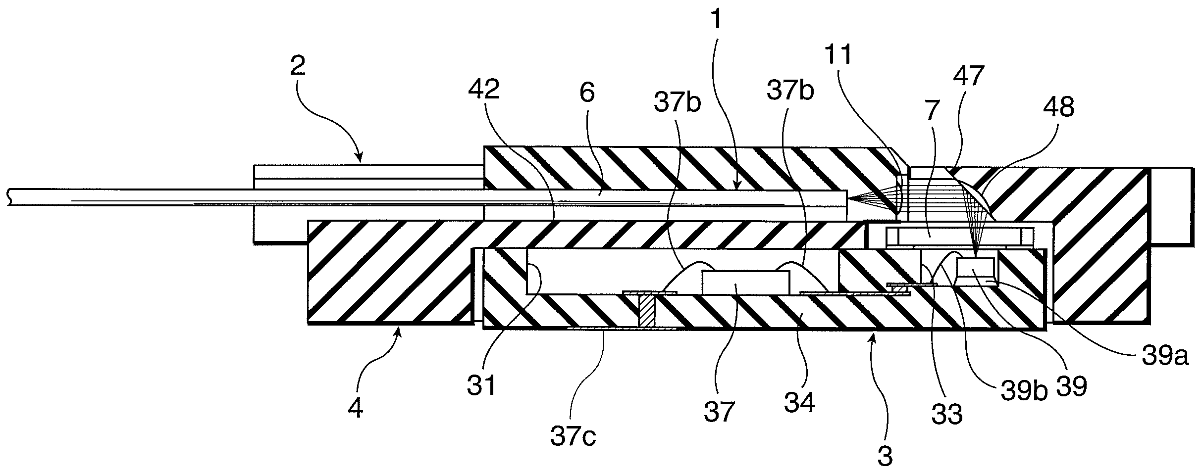
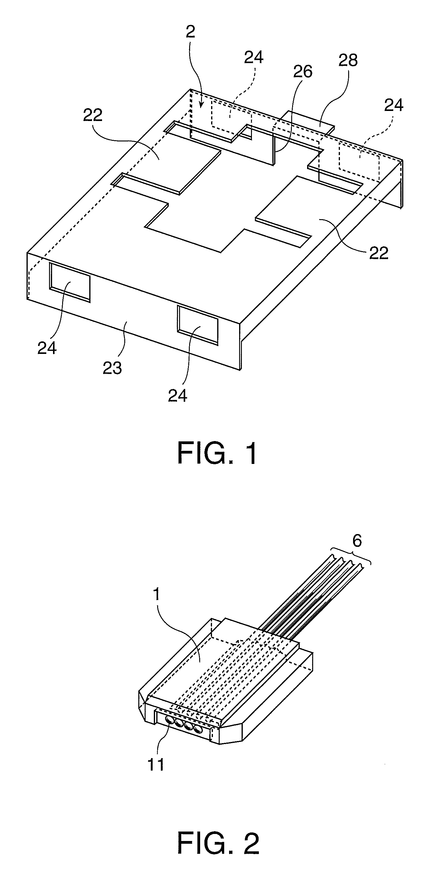
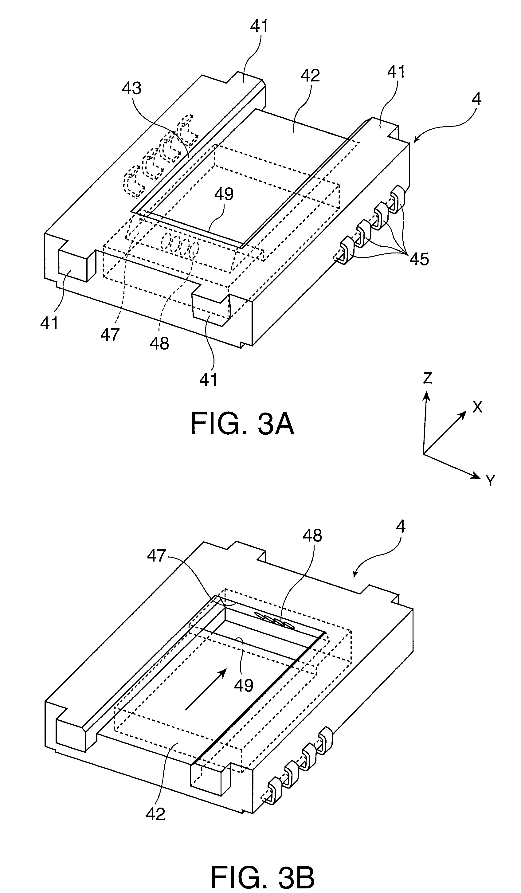
[0035]FIGS. 1-5 are exploded perspective views of an optical module in accordance with an embodiment of the invention. More specifically, the optical module in accordance with the present embodiment includes a clamp 2, an optical plug 1, a resin package 4 and a ceramic package 3. FIG. 1 is a perspective view of the clamp 2, FIG. 2 is a perspective view of the optical plug 1, FIG. 3A is a perspective view of the resin package 4, and FIG. 3B is a perspective view of the resin package 4 viewed from an opposite direction with respect to the X direction. FIGS. 4A and 4B are perspective views of the ceramic package 3. FIG. 5 is a cross-sectional view of the optical module in accordance with the present embodiment, which shows...


PUM


Abstract

An optical module package that optically couples an optical device and an optical fiber includes: a first surface on which an optical plug that supports one end of the optical fiber is mounted; a second surface that intersects the first surface at an angle less than 90 degrees; a reflection lens formed in the second surface; and an opening section that is located at a position opposing to the second surface, and between the reflection lens and the optical device.

Description

[0001]The entire disclosure of Japanese Patent Application No. 2006-188269, filed Jul. 7, 2006 is expressly incorporated by reference herein.BACKGROUND[0002]1. Technical Field[0003]The present invention relates to optical modules that are used for optical communications, and packages used for the modules.[0004]2. Related Art[0005]As a typical example of an optical module that is used for optical communications optical module, an optical module described in Japanese laid-open patent application JP-A-2003-207694 is known. The optical module described in the above document uses a structure in which an optical fiber connector with an array of optical fibers being regularly arranged and bonded thereto is pushed toward a package by a clamp thereby affixing the optical fiber connector to the package.[0006]However, in the optical module described above, the optical fiber connector, the clamp and the package are composed as separate and independent members, such that the work in assembling t...

Claims


Application Information

Patent Timeline
Patent Type & Authority Patents(United States)
IPC IPC(8): G02B6/36
CPCG02B6/4214G02B6/423G02B6/4206H01L2224/48091H01L2224/48227H01L2924/00014H01L2924/3011H01L2924/00H01L2924/3025
Inventor NAGASAKA, KIMIO
Owner SEIKO EPSON CORP
Why Eureka
Try Eureka