
Aerosol can valve and cover assembly

a technology for aerosol cans and valves, applied in the field of aerosol valves, can solve the problems of difficult assembly of valves, inability to effectively prevent inadvertent dispensing operations, and high cost of valves

Active Publication Date: 2010-01-05
CLAYTON
View PDF14 Cites 44 Cited by
  • Summary
  • Abstract
  • Description
  • Claims
  • Application Information

AI Technical Summary

Benefits of technology

"The present invention is related to a cover assembly for a valve of an aerosol can. The cover assembly includes a detachable portion that prevents the cover from being rotated to a position where the movement of the trigger will activate the valve, thereby controlling the dispensing operation of the valve. The cover assembly also includes a trigger pivotally coupled to a rotatable cover, which allows the cover to be raised or lowered to control the dispensing operation of the valve. The detachable portion of the assembly prevents accidental activation of the valve and provides a safer and more reliable assembly for aerosol cans."

Problems solved by technology

A problem with these aerosol container products is that the dispensing valve may not effectively prevent inadvertent dispensing operation prior to delivery to the end user, or when the container is stored after intermittent use.
Furthermore, these valves typically comprise numerous parts made from various materials that can make the valves difficult and expensive to assemble.

Method used


Image

  • Aerosol can valve and cover assembly
  • Aerosol can valve and cover assembly
  • Aerosol can valve and cover assembly

Examples


Embodiment Construction

[0016]The following description of the embodiments is merely exemplary in nature and is in no way intended to limit the invention, its application, or uses.

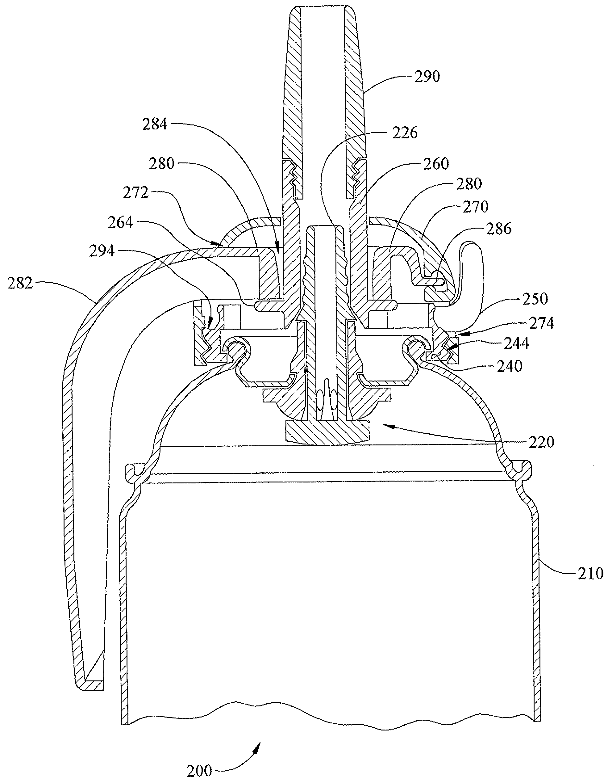
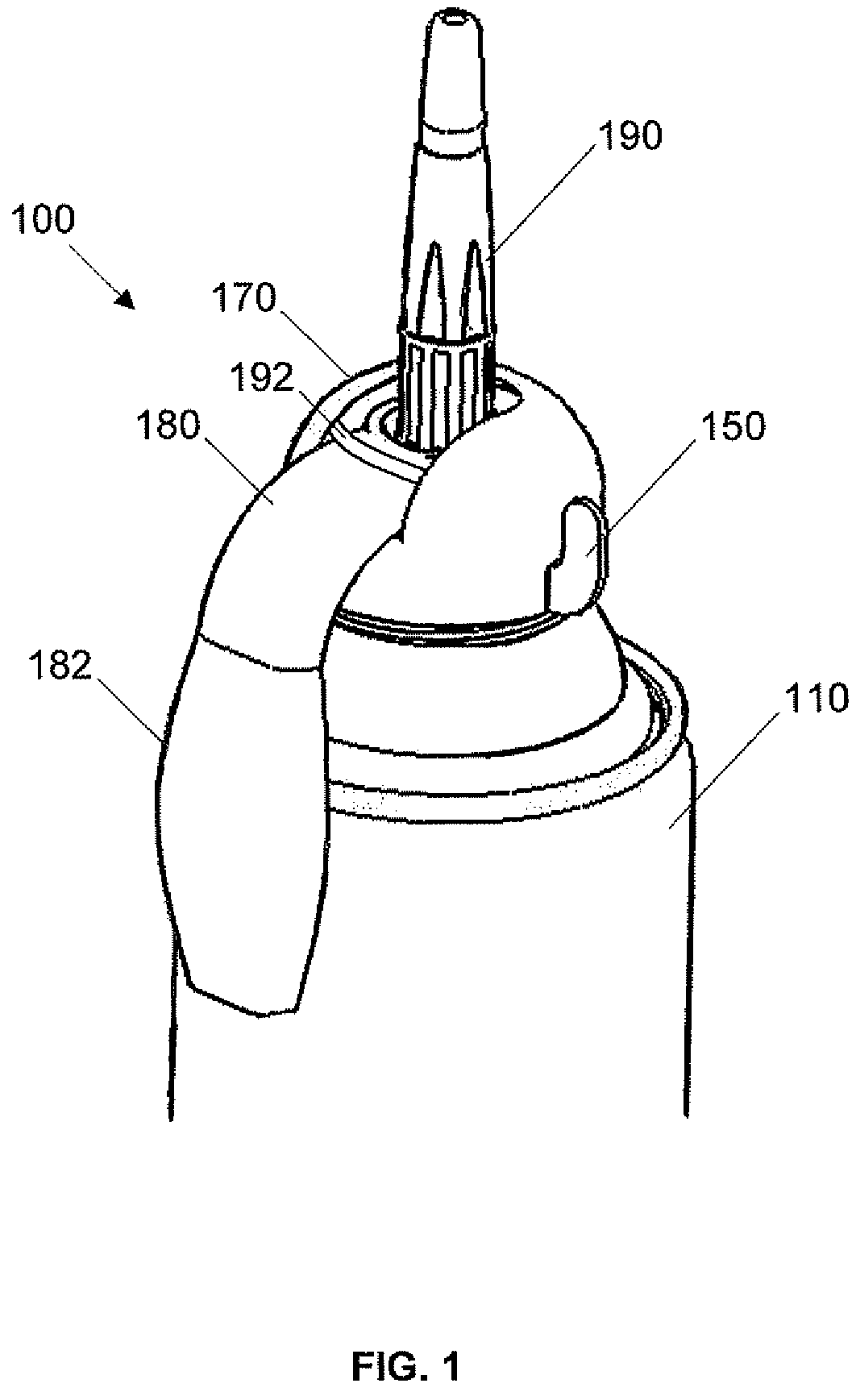
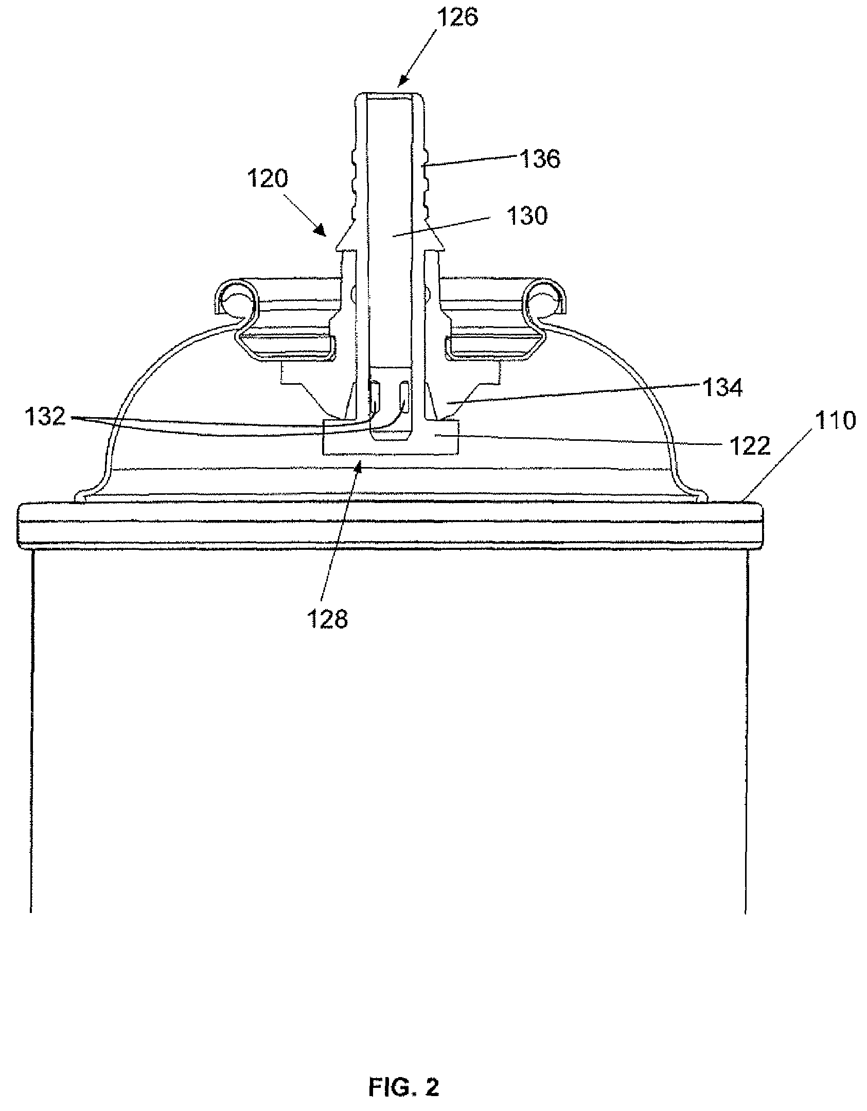
[0017]One embodiment of cover and trigger assembly for an aerosol can or container constructed according to the principles of this invention is indicated generally as 100 in FIG. 1. The cover assembly 100 generally comprises a cover member 170, a trigger member 180 having a handle portion 182, and a nozzle portion 190 in communication with the outlet of a dispensing valve on the aerosol can 110. The cover assembly 100 is configured to be secured onto an aerosol can 110 having a dispensing valve thereon (not shown in FIG. 1), which valve may be actuated to permit dispensing operation of the contents of the aerosol can or container 110 The cover assembly may optionally comprise a detachable portion 150 that resists movement or rotation of the cover 170 to a position which permits dispensing operation of the valve, as will be explai...


PUM


Abstract

A cover and trigger assembly is provided that includes having a valve that can be actuated for dispensing the contents of the can through an outlet of the valve. The assembly includes an annular component having a helical surface is secured to the can, and a cover coupled to the annular component. The cover has an opening through which a trigger extends, and the cover is rotatable relative to the helical surface on the annular component for rotatably raising or lowering the cover relative to the annular component. The raising or lowering of the cover respectively prohibits or permits movement of the trigger member to actuate the valve, thereby controlling dispensing operation of the valve.

Description

FIELD OF THE INVENTION[0001]This invention relates to valves for aerosol cans, and in particular to an improved aerosol valve with a trigger dispensing control feature.BACKGROUND OF THE INVENTION[0002]Aerosol containers that dispense liquid or foam products are often packaged in aerosol cans with a pressurizing agent, which acts as a propellant for dispensing the product. These aerosol cans include a dispensing valve that may be operated to dispense the contents of the aerosol container as needed. A problem with these aerosol container products is that the dispensing valve may not effectively prevent inadvertent dispensing operation prior to delivery to the end user, or when the container is stored after intermittent use. Furthermore, these valves typically comprise numerous parts made from various materials that can make the valves difficult and expensive to assemble.SUMMARY OF THE INVENTION[0003]The present invention relates to a cover assembly for a valve for dispensing the conte...

Claims


Application Information

Patent Timeline
Patent Type & Authority Patents(United States)
IPC IPC(8): B65D83/20
CPCB65D83/22B65D83/201
Inventor LOTT, JOSEPH C.RUESCHHOFF, KENNETH J.BERGER, RICHARD A.
Owner CLAYTON
Learn More