Efficiency dehumidifier drier with reversible airflow and improved control

a dehumidifier and airflow technology, applied in the direction of laundry driers, lighting and heating apparatus, washing apparatus, etc., can solve the problems of complex need, difficulty in adjusting the degree of success, and inability to meet the needs of users, so as to improve the effect of releasing moisture more slowly and improving the efficiency of the system

Inactive Publication Date: 2007-01-25
DELTA V TECH
View PDF15 Cites 50 Cited by
  • Summary
  • Abstract
  • Description
  • Claims
  • Application Information

AI Technical Summary

Benefits of technology

[0061] It is also preferable to configure this variable evaporator heat exchange area such that two or more of the sub streams of drying gas pass over separate sections of the evaporator heat exchange area. The effective evaporator heat exchange area is then adjusted according to the specific drying gas flow configuration such that the drying gas flowing across the active evaporator area is always cooled sufficiently to condense and remove liquid from the drying gas in combination with adjusting total refrigerant flow through the compression system while keeping the total effective heat pump condenser heat exchange area in the drying gas stream constant. This will have the initial benefit of keeping the evaporating and condensing temperatures within the allowed ranges for the compressor system. This will also have the benefit of driving the drying process at higher efficiency over a range of drying conditions since it will enable the wasteful excess moisture removal capacity of the heat pump system to be turned down, while keeping the evaporating temperature at the optimum value for efficient operation as the material dries and inherently releases moisture more slowly. Another benefit is realised by keeping the condenser fully active throughout the drying process which mininises the condensing temperature difference so the efficiency of the system is kept near its maximum as the drying gas temperature rises during the drying process. This enables the operating temperature to be increased to increase the driving force for drying, while remaining within the compressor operating limits, when the inherent drying rate naturally drops off later in the drying process.
[0062] Thus with this preferred embodiment, the performance of the drier can be optimised during the start of the drying process at high heat pump loads when the temperature is lowest, and the humidity highest using a high refrigerant flow in the heat pump and a large active evaporator area. Yet the present invention will still permit the drier to operate effectively and efficiently at high temperatures and low humidity under low heat pump loads, as required to complete the drying process as fast and efficiently as possible using a lower refrigerant flow, lower active evaporator area, and higher active condenser area per unit refrigerant flow and also permit heat transfer to enable the higher dry bulb temperatures for the drying gas flow to be achieved more efficiently and the moisture from the drying gas stream to continue to condense and be removed from the process. Furthermore, all of this is accomplished without disrupting the drying gas flow or negatively affecting the pressure drop in the drying gas circuit.

Problems solved by technology

This process is often relatively rapid but energy inefficient.
Alternative drying methods using heat pump based drying systems have been generally known in industrial applications including timber drying for a number of years but they have had varying degrees of success based on limitations in performance, control and efficiency.
This need is complicated by the fact that the control of a heat pump dehumidifier system and the drying process parameters themselves are linked by multiple feed-back processes that are fundamentally different from the more commonly practiced but less efficient heat-and-vent drying systems.
One further problem that has developed more recently as part of the high drying speed is that the characteristics of the dried material are less suitable to the end users of the dried product.
In the case of timber, these difficulties include kiln brown stain and internal checking.
Another problem is the uneven drying that results when the hot drying gas, typically air, is passed over the material to be dried in a single direction throughout the process.
Material that is exposed to the hot drying gas first dries more quickly than the material further downstream in the configuration and can become over-dry on one side and under-dry on the other, with adverse quality implications.
However this problem of uneven drying is still present in heat pump driven kilns because the heat pump design has so far prevented any efficient reversing of the drying gas flow during operation.
Another problem that is present with heat-and-vent kilns is their fundamentally poor energy efficiency.
Although they can sometimes be driven with waste heat systems, low temperature heat-and-vent systems typically require a high capital investment relative to their productivity which diminishes their attractiveness.
However, the controls and louvers in such a system will need to be positioned in the active drying gas flow path which tends to increase the pressure drop through the drying gas circuit which cuts into the efficiency gains for the process.
Another unsatisfactory aspect is that having critical mechanical moving parts in the kiln reduces system reliability.
Louver type airflow controls tend to fail in the aggressive environment and this can result in damage to the product or the heat pump.
Although effective from an efficiency perspective, the capital cost and operating difficulties associated with such a system are a significant disadvantage.
Just as with the effort to reduce the capital cost of a drying apparatus, the effort to improve its efficiency is never completely finished.
While effective in the air conditioning application, this functionally series configuration is not flexible enough to work effectively in heat pump drying applications.
Cooperman's work clearly improves the performance of a heat pump system with an ambient air heat source where a constant quantity of heat is required at the condenser but this is not suitable for a heat pump drying system which has widely varying requirements on the heat pump condenser side as well.
There is no capacity to vary the heat output through the condenser or the flow of refrigerant through it.
As for Cooperman's work, maintaining a strictly constant supply of heat is not well suited for drying applications.
Also, there is no capacity to vary the heat output through the condenser or the flow of refrigerant through it.
Again, there is no capacity to vary the heat output through the condenser or the flow of refrigerant through it.
The difficulty with these last three attempts to improve heat pump performance through evaporator area control is that they are specifically designed for use in open environments and to provide a constant supply of heat through the condenser.
The second is that the heat flow required from the condenser drops off significantly as the material dries.
This makes such open heat source, constant heat supply rate designs present in the prior art ill suited for drying applications.
Another problem with many existing heat and vent kiln systems is the highly prominent vapour plume associated with the warm wet drying gas vented from the unit.
Although heat pump based systems with essentially closed loop drying gas configurations essentially solve the plume problem, they do not possess other desirable characteristics of the heat and vent systems.
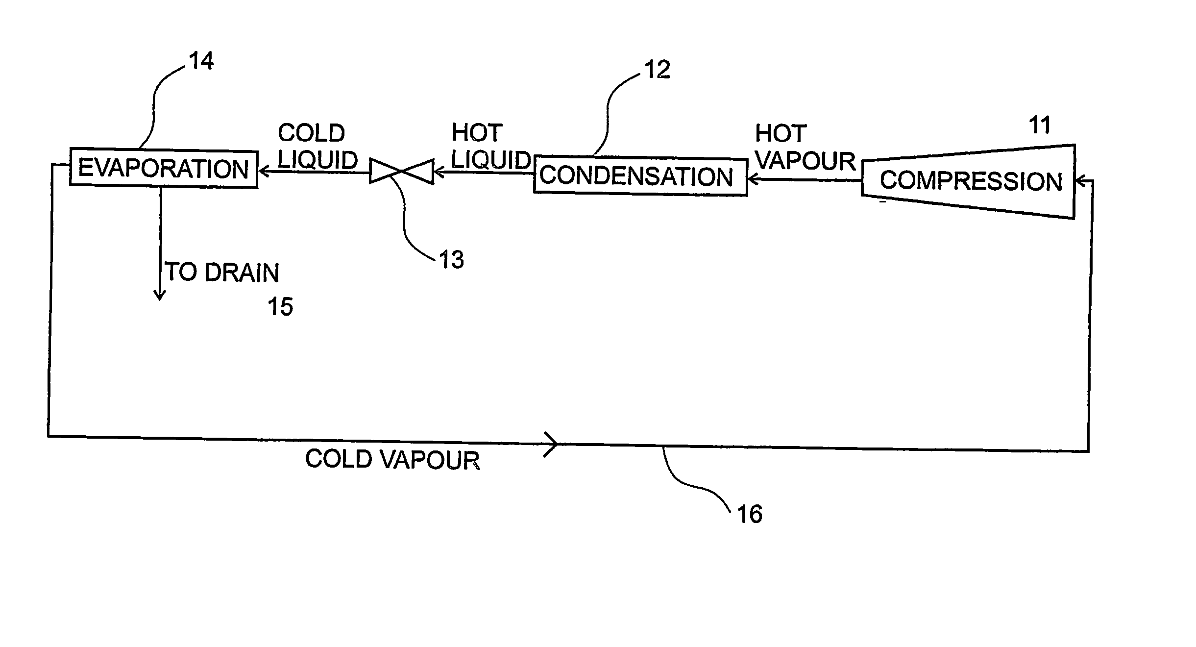
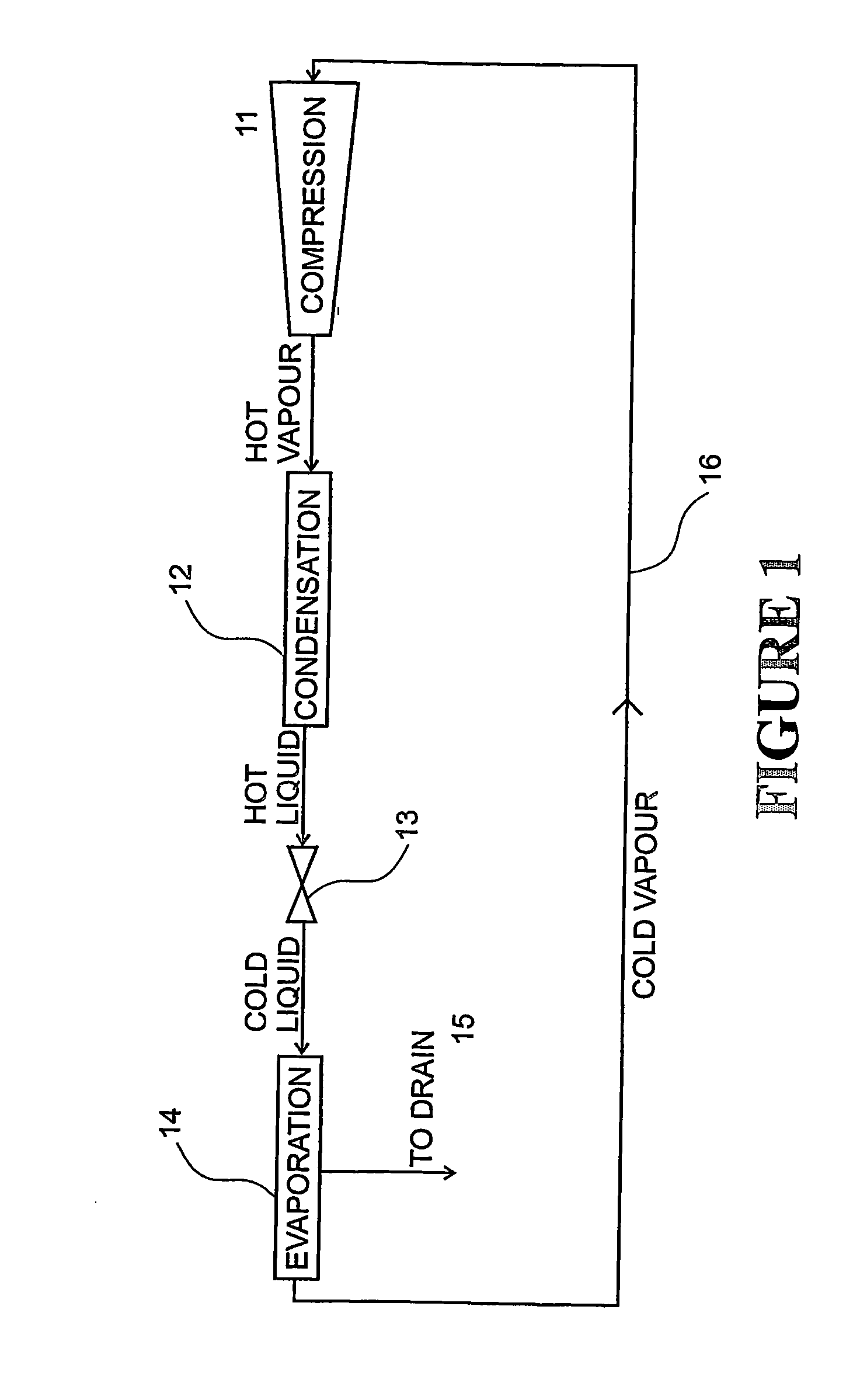
One of these specific characteristic problems with heat pump driven systems is the difficulty in reversing the drying gas flow in the drying chamber to promote even drying of the material as is done for heat-and-vent driers.
This problem results from the specific configuration of the heat pump condenser, which condenses the heat pump working fluid and heats the recirculating drying gas stream, and the heat pump evaporator, which evaporates the heat pump working fluid and removes some of the moisture from the recirculating drying gas stream by cooling it and inducing water condensation.
Drying gas flow cannot be reversed in this system without dramatically reducing the drying capacity and efficiency, since it would result in the evaporator wastefully recooling part of the heated drying gas from the condenser and removing less moisture relative to the amount of heat removed.
Because drying gas flow reversal in the existing dehumidifiers is not practical, some dehumidifier timber kiln operators have attempted to overcome the problem of uneven drying by leaving the kiln fans running for long periods without running the dehumidifier, in order to even-up the moisture content of the boards in different parts of the stack.
But this reduces the kiln production rate and efficiency and thus reduces its profitability.
Without any details of the method of the heat pump dehumidification of the air or any claims relating to an apparatus to conduct their method, the problem remains.
The reversible air circulation system in U.S. Pat. No. 5,276,980 by Carter and Sprague is nominally applicable to heat pump systems but still has problems with its application.
One difficulty with this system is the capital cost of the complex air drying gas ducting system required for air off-take and return, and the cost of operating the fans needed to deliver the required air volumes.
The system has no capability of reversible drying gas flow nor does it provide for any recirculation or regeneration of the drying gas stream in a closed or semi-closed loop configuration.
As a result, in all but extremely high temperature ambient conditions, their unit is not able to operate as efficiently as a closed loop system.
As such, these other attempts to control heat-and-vent processes do not address the problem for high efficiency heat pump driven systems with nominally closed loop drying gas recycle streams.
Again, this method does not address the operational limits and opportunities associated with a heat pump driven system.
Although they follow a schedule with a nominally constant wet bulb temperature in the drying gas during the main part of the drying process, they decrease the wet bulb temperature at the end of the process which would cause difficulties with a heat pump dehumidification process.
Since there is no heat pump dehumidification addressed in this work, it is also not able to address the efficiency issues associated with the simultaneous control of a heat pump dehumidifying system.
With the lower temperature differences present in heat pump dehumidification systems, this is not a practical measured variable for control and thus the problem remains.
This method has the disadvantage that, as the product dries and the wet bulb temperature falls in response, the dehumidifier drying capacity also falls, typically reducing the drying rate and the drying efficiency unnecessarily.
If the temperature is increased too early, the product may be damaged and lose value.
If the adjustment takes place too late, the drying time will be unnecessarily extended, with accompanying loss of productivity and increased drying costs.
The control strategy suffers from similar limitations to those of Lewis in U.S. Pat. No. 4,250,629 and as a result does not fully address the problem of integrated control of the drying process and the heat pump system.

Method used


Image

  • Efficiency dehumidifier drier with reversible airflow and improved control
  • Efficiency dehumidifier drier with reversible airflow and improved control
  • Efficiency dehumidifier drier with reversible airflow and improved control

Examples


Embodiment Construction

[0078] The present invention is a process and apparatus to improve the heat pump based or heat integrated drying of timber and other materials. A preferred embodiment of the invention involves conducting the heating and cooling / partial condensing of two sub-streams of drying gas flow by indirect heat exchange against the respective heat pump condenser and evaporator in functionally parallel sub-stream flow paths such that at least one sub stream exchanges heat with substantially only the heat pump evaporator and at least one other sub stream exchanges heat with substantially only the heat pump condenser with the ability to efficiently reverse the direction of drying gas flow through the corresponding heat exchangers. Another preferred embodiment of the invention involves conducting the cooling / partial condensing of one or more sub streams of drying gas flow by indirect heat exchange against the heat pump evaporator configured such that each of these sub streams is in a functionally ...


PUM


Abstract

An apparatus and process including a heat sink exchanger (26) to cool and condense liquid out of a drying gas with a heat transfer surface arranged to exchange heat with a first sub-stream of the drying gas and a heat source heat exchanger (27) arranged to exchange heat with a second sub-stream of a drying gas and arranged in a functionally parallel configuration with said heat sink heat exchanger (26) so that each of said drying gas sub-streams exchanges heat with one of the two said heat transfer surface per cycle through the heat exchange system and a gas movement device (35) for propelling the drying gas through the heat exchanger system in either a forward or reverse flow path direction. The apparatus and process can also include controlling the amount of heat rejected from apparatus (26) based on maintaining the wet bulb of the drying gas nominally constant and controlling the amount of refrigerant in the heat exchanger circuit based on maintaining the dry bulb temperature of the drying gas within certain limits.

Description

FIELD OF THE INVENTION [0001] The present invention relates to the drying of materials using a heat pump or heat integrated dehumidifier system to move energy to evaporate liquid from wet material. It has particular application to the drying of timber but is also well suited for numerous other drying processes. BACKGROUND TO THE INVENTION [0002] Most milled timber and many other materials dried on an industrial scale are currently dried by kilns operating on a heat-and-vent principle where ambient air is heated by indirect contact with steam or by some other high temperature heat source, passed over the timber or other material to be dried, and vented back to the atmosphere. This process is often relatively rapid but energy inefficient. Alternative drying methods using heat pump based drying systems have been generally known in industrial applications including timber drying for a number of years but they have had varying degrees of success based on limitations in performance, contr...

Claims


Application Information

Patent Timeline
Patent Type & Authority Applications(United States)
IPC IPC(8): F26B19/00F26B3/00F26B21/02F26B21/08
CPCD06F58/206F26B2210/16F26B21/086F26B21/026
Inventor SCHARPF, ERIC WILLIAMGERALD, CEDERICSUN, ZHIFIA
Owner DELTA V TECH
Why Eureka
Try Eureka