Light source comprising a light emitter arranged inside a translucent outer envelope

a technology of light emitter and outer envelope, which is applied in the direction of light source semiconductor devices, lighting and heating apparatus, coatings, etc., can solve the problems of insufficient wide emission profile in a plane perpendicular to the base of the led, relative low efficiency, etc., to improve efficiency, reduce scattering losses, and enhance system efficiency

Active Publication Date: 2012-06-21
KONINKLIJKE PHILIPS ELECTRONICS NV
View PDF14 Cites 72 Cited by
  • Summary
  • Abstract
  • Description
  • Claims
  • Application Information

AI Technical Summary

Benefits of technology

[0010]An effect of the light source according to the invention is that the spatial emission profile of the light source according to the invention is increased. Because the light emitter according to the invention comprises the translucent inner envelope comprising the diffuser, and because the light emitter is positioned at a distance from the imaginary base-plane, more light is emitted in a direction towards the imaginary base-plane, thus increasing the spatial emission profile of the light source according to the invention compared to the retrofit lamp as shown in FIG. 3 of the cited non-prepublished patent application.
[0043]In an embodiment of the light source, a wall of the outer envelope facing the inner envelope comprises an organic lumophor layer for converting light emitted by the light emitter into light of a longer wavelength. A benefit when using a lumophor layer is that the lumophor layer substantially has no scattering which further enhances the efficiency of the system. Any scattering in the light source leads to some loss of light. Having a light conversion layer without scattering would reduce the scattering losses and would thus improve the efficiency. A further benefit of organic lumophor material is that the lumophor may be chosen to have a relatively small Stokes-shift. The inventors have found that when using an organic lumophor material which converts light while having a Stokes-shift below 150 nanometers or, more preferably, below 100 nanometers, the emission spectrum of the light emitted by the lumophor material remains narrow, and the emission spectrum of the light source is prevented from expanding into the deep-red range of the spectrum. As the lumophor material typically is used to contribute light having the color red, the limitation of the emission spectrum enables to limit the infrared contribution of the organic lumophor material and as such ensure good efficiency. In such a light source a first luminescent material may, for example, convert the blue light from the light emitting device into green light, and the lumophor material may convert part of the green light into red light. Other color combinations may be chosen without departing from the scope of the invention.

Problems solved by technology

A well known drawback of the incandescent light sources is that they have a relatively low efficiency as they emit a large part of their energy in the infrared part of the electromagnetic spectrum.
A disadvantage of the above-mentioned retrofit lamp is that the emission profile in a plane perpendicular to the base of the LED is not wide enough.

Method used


Image

  • Light source comprising a light emitter arranged inside a translucent outer envelope
  • Light source comprising a light emitter arranged inside a translucent outer envelope
  • Light source comprising a light emitter arranged inside a translucent outer envelope

Examples


Embodiment Construction

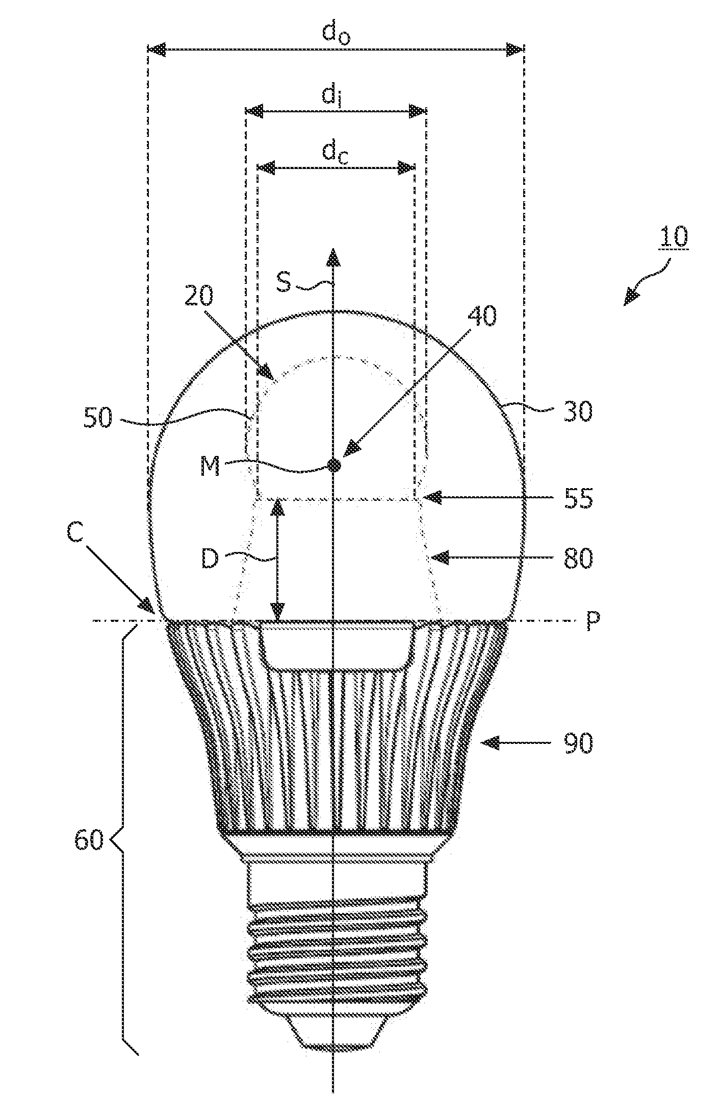
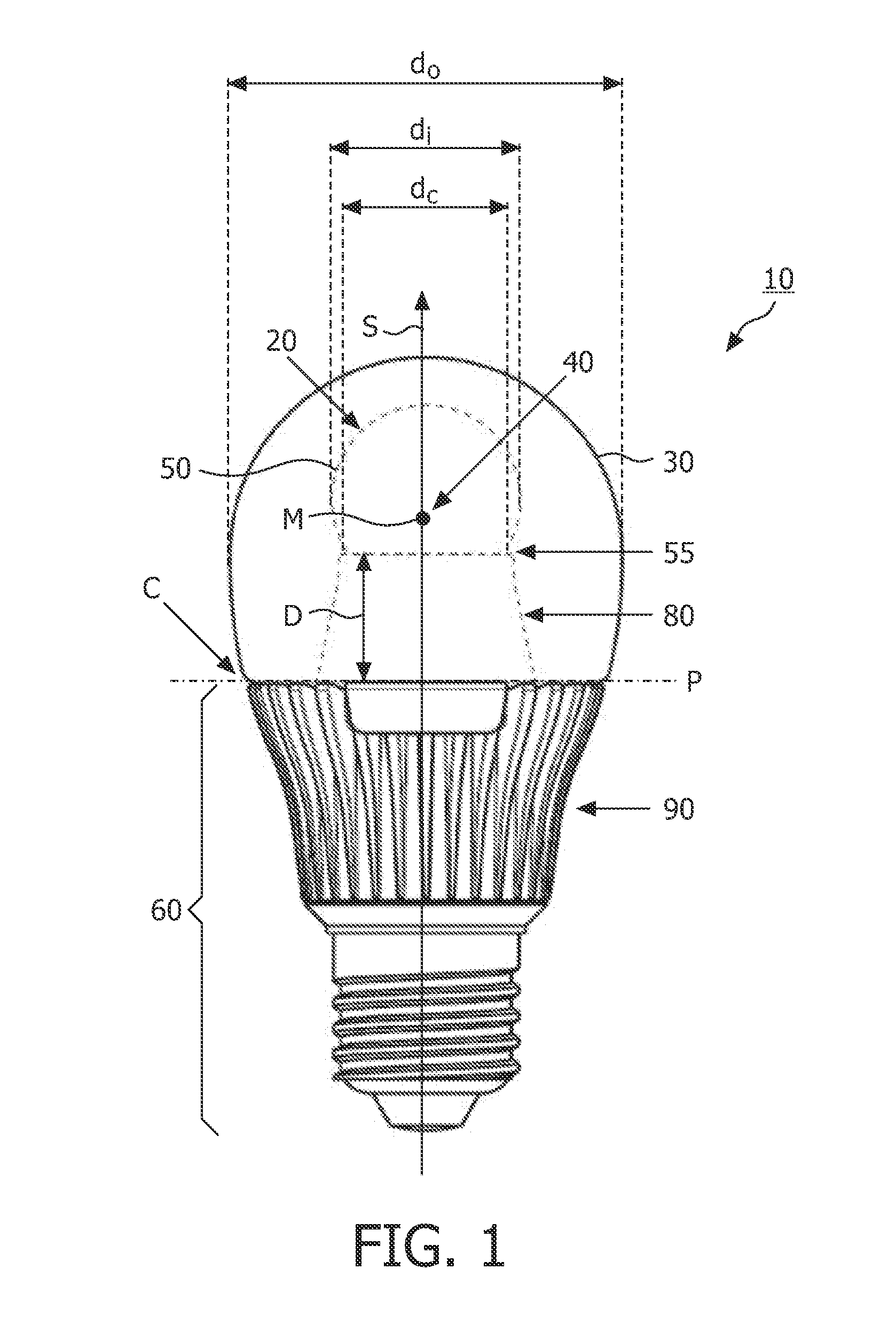
[0052]FIG. 1 shows a side-view of a light source 10 according to the invention. The light source 10 comprises a light emitter 20 which is positioned inside a translucent outer envelope 30. The light emitter 20 comprises a light emitting device 40 (see FIG. 4) which is at least partially surrounded by a translucent inner envelope 50 comprising a diffuser (not indicated) for diffusing at least a part of the light emitted by the light emitting device 40. The diffuser may be integrated in the wall of the inner envelope 50 or may be applied as a layer to an inner wall or an outer wall of the inner envelope 50. A diameter di of the translucent inner envelope 50 is smaller than a diameter do of the translucent outer envelope 30. The translucent outer envelope 30 is connected to a base 60 which is usually not translucent. Furthermore, the translucent outer envelope 30 comprises a symmetry axis S. In FIG. 1 also an imaginary base-plane P is indicated via a dash-dotted line. This imaginary ba...


PUM

PropertyMeasurementUnit
anglesaaaaaaaaaa
widthaaaaaaaaaa
peak wavelengthaaaaaaaaaa

Abstract

The invention relates to a light source (10, 12) comprising a light emitter (20) arranged inside a translucent outer envelope (30, 32). The light emitter comprising a light emitting device (40) and comprising a translucent inner envelope (50) at least partially surrounding the light emitting device, the translucent inner envelope comprising a diffuser. A diameter (di) of the translucent inner envelope is smaller than a diameter (do) of the translucent outer envelope. The translucent outer envelope is connected to a base (60) not being translucent. The translucent outer envelope further comprises a symmetry axis (S). An imaginary base-plane (P) is defined substantially perpendicular to the symmetry axis (S) and intersects with a connection point (C) being part of the translucent outer envelope. The connection point is a light transmitting part of the translucent outer envelope at an interface between the translucent outer envelope and the base at a furthest distance from a center (M) of the translucent outer envelope. The light emitter is arranged inside the translucent outer envelope at a distance from the imaginary base-plane away from the base.An effect of the light source according to the invention is that the emission profile of the light source according to the invention is increased.

Description

FIELD OF THE INVENTION[0001]The invention relates to a light source comprising a light emitter arranged inside a translucent outer envelope.BACKGROUND OF THE INVENTION[0002]Light sources comprising a light emitter inside an outer envelope are known per se and include, for example, ancient and well known incandescent light sources. These incandescent light sources are still used extensively as they are relatively easy to manufacture and because many optical systems of, for example, luminaires are designed and optimized to use the light distribution coming from these incandescent light sources. A well known drawback of the incandescent light sources is that they have a relatively low efficiency as they emit a large part of their energy in the infrared part of the electromagnetic spectrum. As such, many replacement light sources have been developed for replacing the incandescent light sources, for example, the compact fluorescent light sources, and, more recently, light sources compris...

Claims


Application Information

Patent Timeline
Patent Type & Authority Applications(United States)
IPC IPC(8): F21V9/16F21V7/00F21V29/00F21V11/00F21V9/40
CPCF21K9/135F21Y2101/02F21Y2111/007F21V29/77F21K9/56F21V3/02F21V3/0481F21V3/00F21K9/232F21K9/64F21V3/12F21Y2107/40F21Y2115/10F21K9/23F21K9/65F21V3/06F21Y2101/00
Inventor HOELEN, CHRISTOPH GERARD AUGUSTHOSKENS, ROGER CORNELIS PETRUSWEGH, RENE THEODORUSAMPALATHUMKAL GEORGE, NIBUDUAN, XIAOQINGRIDER, TIMOTHY HOWARDSHI, LEIANSEMS, JOHANNES PETRUS MARIA
Owner KONINKLIJKE PHILIPS ELECTRONICS NV
Why Eureka
Try Eureka