Image forming apparatus
a technology of image forming apparatus and forming roller, which is applied in the direction of electrographic process apparatus, instruments, optics, etc., can solve the problems of large amount of toner applied in the defective portion of the layer formation, insufficient formation of a toner layer on the developing roller, etc., and achieve the effect of reducing toner and reducing defective images
- Summary
- Abstract
- Description
- Claims
- Application Information
AI Technical Summary
Benefits of technology
Problems solved by technology
Method used
Image
Examples
first embodiment
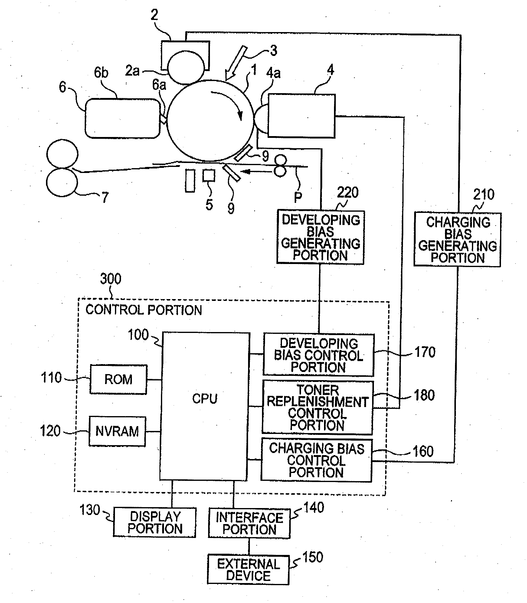
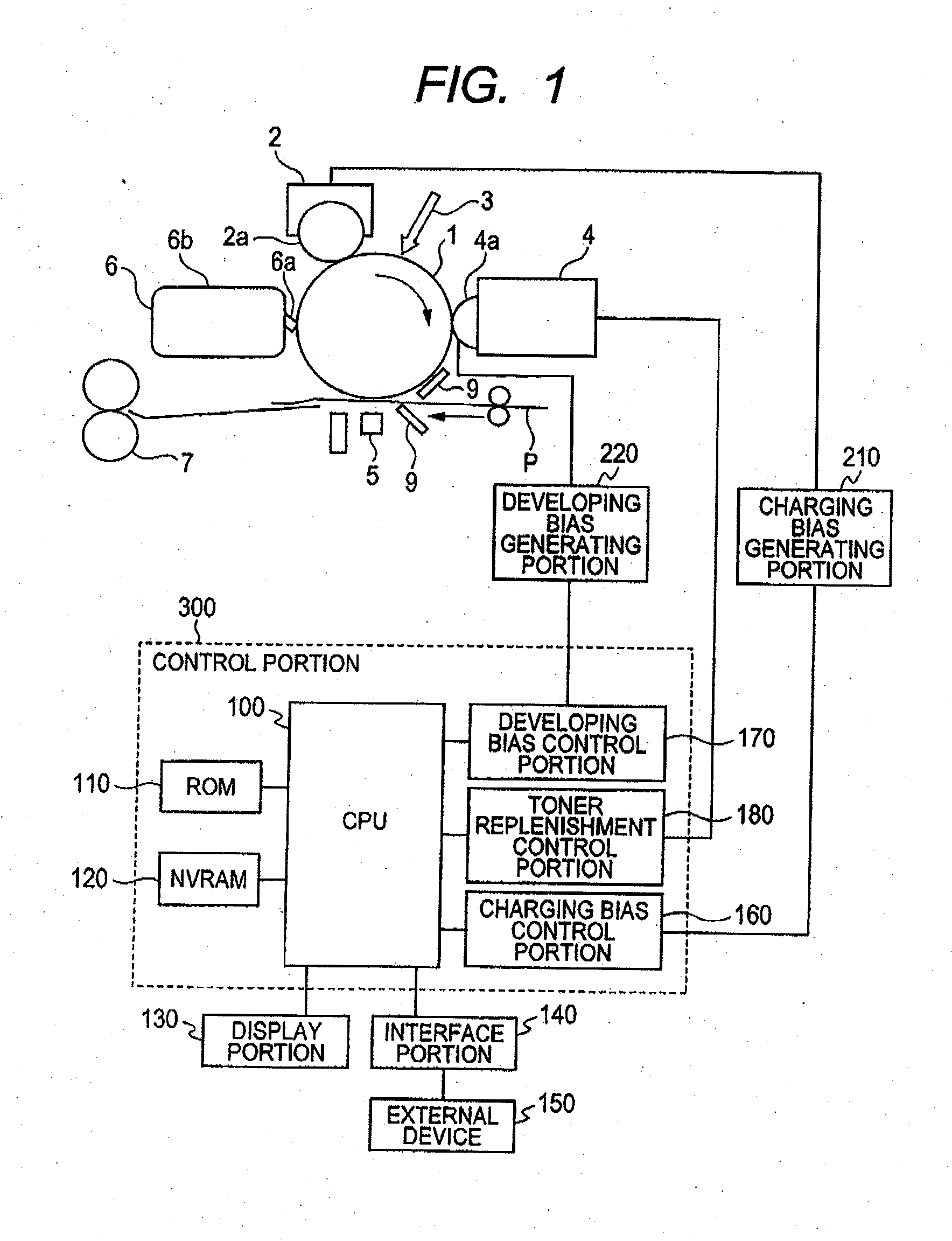
[0042]An image forming apparatus according to a first embodiment will be described. FIG. 1 is a schematic view illustrating a configuration of the image forming apparatus according to the first embodiment. As illustrated in FIG. 1, the image forming apparatus includes a photosensitive member 1 that is an image bearing member having an organic photoconductive photosensitive layer. Further, a charging device (charging unit) 2, an exposure device (exposure unit) 3, a developing device (developing unit) 4, and a cleaning device (cleaning unit) 6, which serve as process devices (process unit) acting on the photosensitive member 1, are provided around the photosensitive member 1. Further; there are provided a transfer device (transfer unit) 5 that transfers a toner image formed on the photosensitive member 1 to a transfer material and a fixing device 7 that fixes the toner image transferred to the transfer material.
[0043]An image forming operation by the image forming apparatus will be de...
second embodiment
[0070]An image forming apparatus according to a second embodiment will be described.
[0071]In the sequence performed in the first embodiment, in which only toner having a certain high charge amount or more is developed onto the photosensitive member, the charge amount has a wide distribution at a low peak value when the number of revolutions of a developing roller is small, and hence, the effect thereof is insufficient.
[0072]Therefore, in the second embodiment, toner having a charge amount higher than the peak of an appropriate charge amount according to the cumulative number of revolutions of the developing roller is developed onto the photosensitive member. Thus, only toner having a charge amount within an appropriate range (up to a predetermined value above or below the peak value) remains in a developing device, which prevents a defective image caused by electrostatic aggregation of toner.
[0073]In the second embodiment, a control portion (control unit) 400 changes a developing el...
third embodiment
[0097]An image forming apparatus according to a third embodiment will be described. In this embodiment, the developing electric field Vcont2 is adjusted according to the detection result of the toner remaining amount detection element 4e in the developing container 40. The other configuration is the same as that of the above-mentioned first embodiment. Therefore, members having the same functions as those of the members therein are designated by the same reference numerals, and description thereof is omitted.
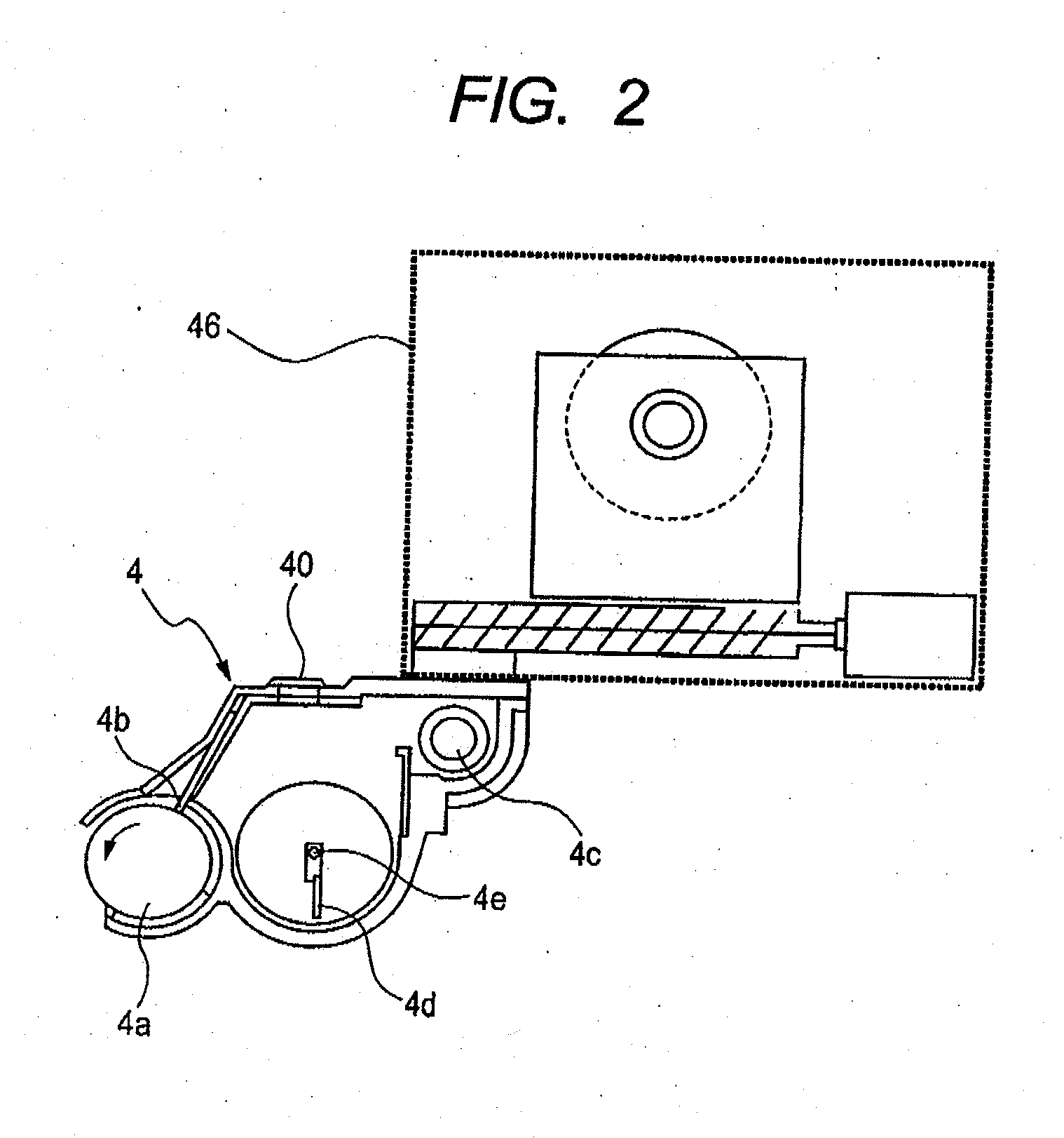
[0098]In this embodiment, the toner remaining amount detection element 4e detects the presence / absence of toner. In a case of “out of toner (toner absence)”, the developer replenishment container 46 replenishes toner to the developing container 40. In the control portion 300 illustrated in FIG. 1, the toner remaining amount detection element 4e detects toner in the developing container 40 every predetermined time. Then, the control portion 300 integrates the detections of toner ...
PUM
 Abstract
Description
Claims
Application Information
 - R&D
- Intellectual Property
- Life Sciences
- Materials
- Tech Scout
- Unparalleled Data Quality
- Higher Quality Content
- 60% Fewer Hallucinations
Browse by: Latest US Patents, China's latest patents, Technical Efficacy Thesaurus, Application Domain, Technology Topic, Popular Technical Reports.
© 2025 PatSnap. All rights reserved.Legal|Privacy policy|Modern Slavery Act Transparency Statement|Sitemap|About US| Contact US: help@patsnap.com


