
Image forming apparatus

Inactive Publication Date: 2005-11-03
CANON KK
View PDF7 Cites 8 Cited by
  • Summary
  • Abstract
  • Description
  • Claims
  • Application Information

AI Technical Summary

Benefits of technology

[0015] It is an object of the present invention to reduce toner scattered from a developing means side and headed to a density detecting member, and to remove ozone near post charging means.

Problems solved by technology

In these color image forming apparatus, in a secondary transfer process of transferring the toner images of plural colors formed on the intermediate transferring belt en bloc to the recording material, if a toner charge amount on the intermediate transferring belt varies from color to color, colors of low and high transferabilities are generated, causing a problem of a reduction in image quality.
According to the conventional configuration, however, problems described below are inherent.
However, depending on an air flow in the post charging device, toner scattered from the developing device may be headed to the patch detecting sensor, causing a problem of sticking of the scattered toner to the patch detecting sensor even if the developing device and the patch detecting sensor are set apart from each other.

Method used


Image

  • Image forming apparatus
  • Image forming apparatus
  • Image forming apparatus

Examples


first embodiment

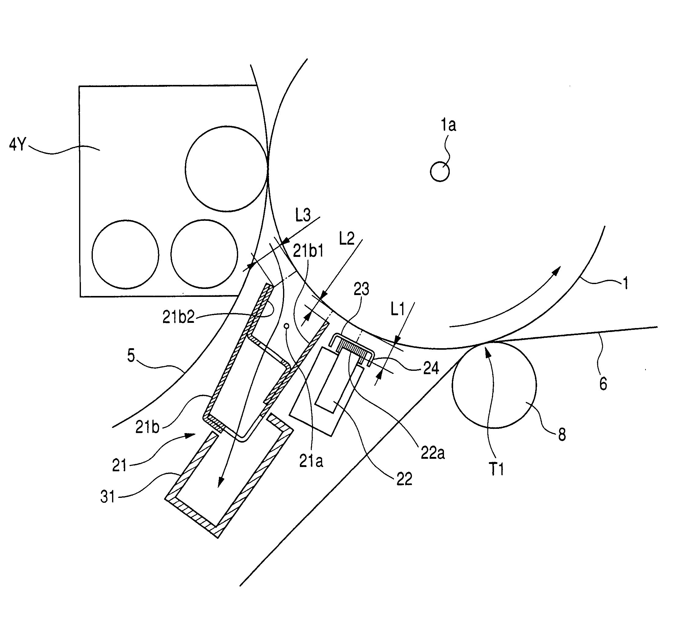
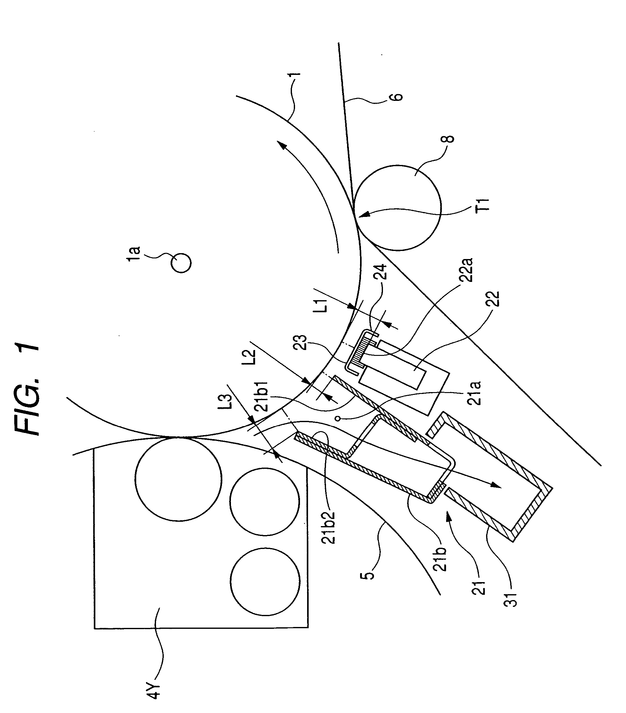
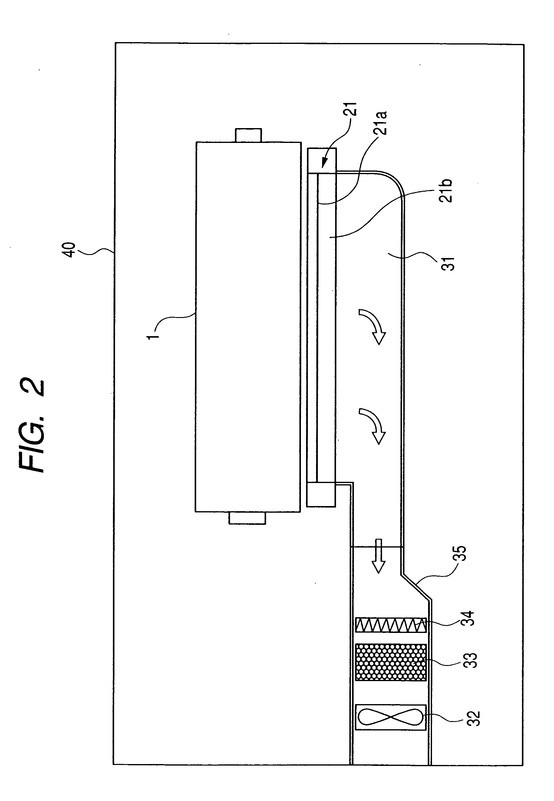
[0021] Next, referring to FIGS. 1 to 3, an image forming apparatus according to an embodiment of the present invention will be described. FIG. 1 is an explanatory diagram showing an arrangement of a post charging device and a density detecting member, FIG. 2 is an explanatory diagram showing an air flow path heading from the post charging device to the outside of the image forming apparatus, and FIG. 3 is a sectional explanatory diagram of the image forming apparatus.

[0022] (Entire Configuration of Image Forming Apparatus)

[0023] First, referring to FIG. 3, an entire configuration of the image forming apparatus according to the first embodiment of will be described. The image forming apparatus of the embodiment is shown in a sectional diagram of a color image forming apparatus of one drum intermediate transferring belt system.

[0024] A photosensitive drum 1 that is an image bearing member is rotatably disposed, a primary charging device 2 is arranged as charging means for charging ...


PUM


Abstract

The image forming apparatus includes a rotatable image bearing member, a latent image forming device, a developing device, a transferring device, a corona charging device which has a discharge wire and a shield member to surround the discharge wire, and which is arranged in a position on a downstream side of a developing position on the image bearing member with respect to a rotational direction of the image bearing member; a density detecting member which detects a density of the toner image on the image bearing member in a position on a downstream side of a discharge position of the corona discharging device with respect to the rotational direction of the image bearing member and on an upstream side of a transfer position; and an air flow path in which an air flow path formed through the inside of the shield member and air is sucked from the image bearing member side toward the shield member. Thus, in the image forming apparatus, toner scattered from the developing device side and headed to the density detecting member can be reduced, and an ozone near post charging device can be removed.

Description

BACKGROUND OF THE INVENTION [0001] 1. Field of the Invention [0002] The present invention relates to an image forming apparatus of an electrophotographic system such as a copying machine or a printer which forms an image on a recording material by using the electrophotographic system, or an image forming apparatus of an electrostatic recording system. [0003] 2. Description of the Related Art [0004] Today, there are available a greater number of electrophotographic image forming apparatus capable of forming color images. One among them is a color image forming apparatus of a so-called one drum intermediate transferring belt system which sequentially forms toner images of yellow, magenta, cyan and black on one photosensitive drum, sequentially superimposes and transfers the toner images on an intermediate transferring belt, transfers the toner images of the intermediate transferring belt en bloc onto a recording material, and forms color images by fixing unfixed toner images of the re...

Claims


Application Information

Patent Timeline
IPC IPC(8): G03G15/00G03G15/16G03G21/00G03G21/20
CPCG03G2215/00042G03G21/206G03G2221/1645G03G2215/027
Inventor KITAYAMA, KUNIHIKO
Owner CANON KK
Learn More