Ozone reducing y-pipe for low cost ozone sensor

a low-cost, ozone-reducing technology, applied in the field of gas detection, can solve the problems of ozone being a very reactive and unstable gas with a short half-life before it reverts back to oxygen, affecting respiratory health, and affecting forests, etc., to achieve the effect of eliminating ozone and reducing costs

Inactive Publication Date: 2011-08-18
GENERAL ELECTRIC CO
View PDF5 Cites 9 Cited by
  • Summary
  • Abstract
  • Description
  • Claims
  • Application Information

AI Technical Summary

Benefits of technology

A primary benefit realized by the ozone detection system is the ability to generate data from a reduced ozone gas sample that is then used to calculate actual ozone levels above those that can be accurately detected by lower cost sensors, so that the appliance can operate to eliminate ozone from ozone-rich samples.

Problems solved by technology

However, ozone resulting from human activity at or close to the ground is a main component of smog, which adversely affects respiratory health, agricultural crops, and forests.
Ozone is a very reactive and unstable gas with a short half-life before it reverts back to oxygen.
This powerful oxidant will have significant long term negative effects on our water sources.
Current ozone sensing technologies are not easily adapted to work in consumer grade appliances.
While others such as electrochemical type sensors are very expensive and last only approximately two years.
Furthermore, current lower cost ozone sensors do not have adequate resolution at higher concentrations of ozone such as around 20 parts per million or higher.
Even in light of recent advances, the industry continues to lack a cost effective ozone detection system, useful in consumer grade appliances, with the ability to detect high ozone concentration levels by reducing total ozone content and then calculating an undiluted sample gas concentration using conventional ozone type sensors.

Method used


Image

  • Ozone reducing y-pipe for low cost ozone sensor

Examples


Embodiment Construction

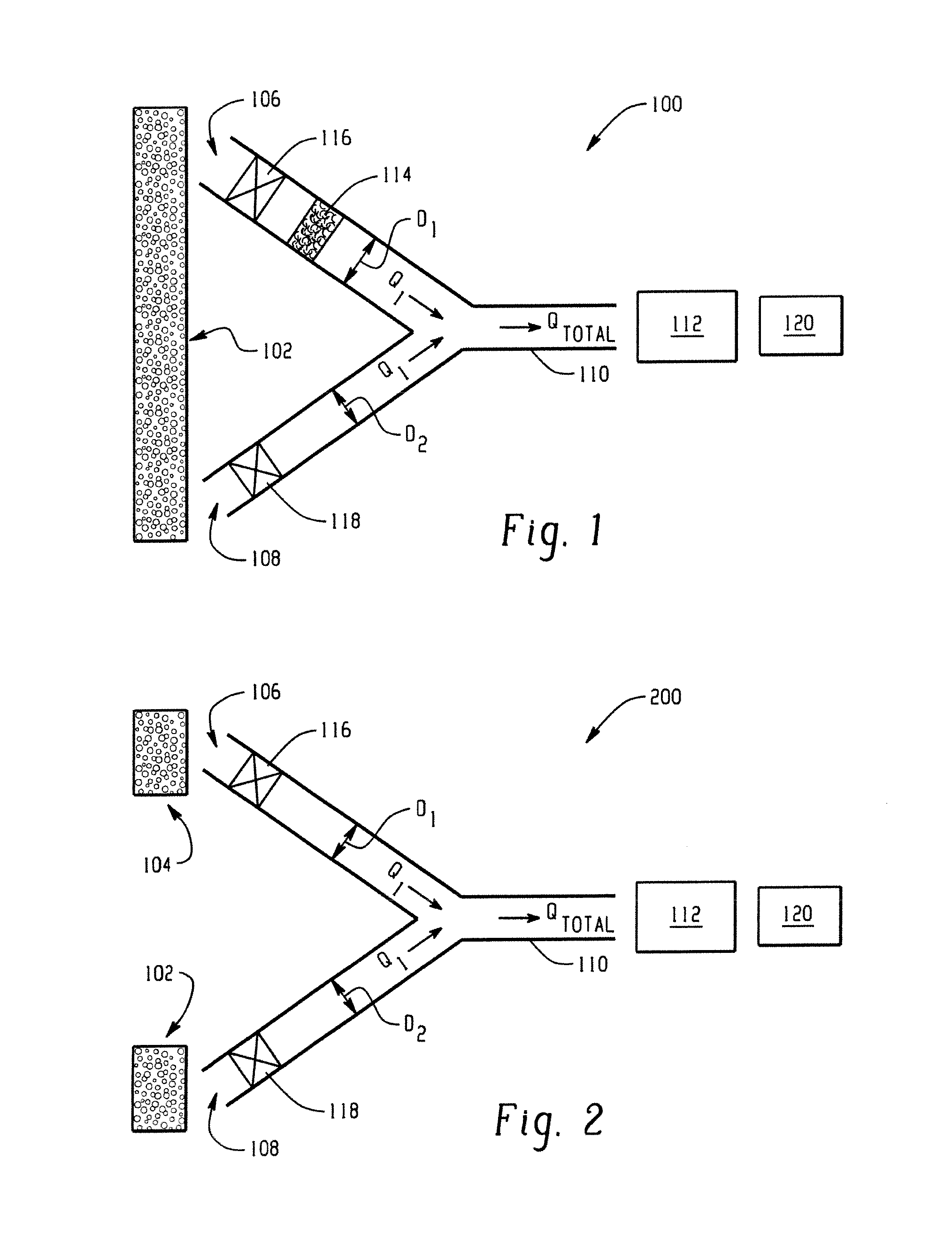
The current inventive ozone detection system has the ability to measure ozone in small and large concentrations using a relatively low cost ozone sensor that generally is capable of ozone detection only at much lower levels. This is achieved in the inventive system, by diluting the original sample, calculating the ozone level in the diluted sample, and using this data to calculate actual ozone levels in the original sample gas. This eliminates the need to use more sensitive, costly sensors and yet still allows the appliance to be suitable for use in higher ozone environments. For example, the current ozone sensing system may be incorporated into a deodorizing- or sanitizing-type consumer product such as those products set forth in U.S. Ser. No. 12 / 621,947 to our common assignee, among others. In accordance with one embodiment of the present disclosure, a sensor operative to detect ozone concentrations in the range of 0.5-10 ppm is used to sense the ozone concentration of gases havin...


PUM

PropertyMeasurementUnit
concentrationaaaaaaaaaa
diameter D1aaaaaaaaaa
diameter D2aaaaaaaaaa

Abstract

An ozone detection system includes a source of sample gas containing a concentration of ozone. The system further includes a first airflow passageway for receiving a first sample of gas from the source. The first airflow passageway includes a catalytic scrubber to reduce ozone content in the sample gas and a second airflow passageway receives a second sample of gas from the source. A third airflow passageway results from the convergence of the first and second airflow passageways wherein the reduced sample gas and the unaltered sample gas are combined to form a diluted sample gas. A sensor is provided for sensing the ozone concentration in the diluted sample gas received from the third airflow passageway. A processor is provided operative to calculate the actual concentration of ozone in the sample gas as a function of the sensed concentration of the diluted sample.

Description

BACKGROUND OF THE DISCLOSUREThe present disclosure relates to gas detection, more specifically to an ozone detection system and method. The ozone detection system finds particular application in consumer grade appliances, although it will be appreciated that selected aspects may find use in related applications encountering the same issues of a cost effective ozone sensor with good resolution at high ozone concentrations in order to regulate proper ozone levels.Ozone (O3) is a colorless gas which has both beneficial and detrimental effects on health and the environment. Ozone is a naturally occurring component resulting from a lighting storm giving that fresh air smell. It can be produced by the ultraviolet rays of the sun reacting with the Earth's upper atmosphere, which creates a protective ozone layer, or it can be created artificially with an ozone generator. However, ozone resulting from human activity at or close to the ground is a main component of smog, which adversely affec...

Claims


Application Information

Patent Timeline
Patent Type & Authority Applications(United States)
IPC IPC(8): G01N31/10
CPCY10T436/206664G01N33/0039Y02A50/20
Inventor SCHORK, BRIAN MICHAELBESORE, JOHNALLIMALLI, YOGESH KUMARMILLER, LARRY
Owner GENERAL ELECTRIC CO
Why Eureka
Try Eureka