Pipe structure

a technology of pipe structure and pipe body, which is applied in the direction of machine/engine, mechanical equipment, surface coverings, etc., can solve the problems of not removing hazardous components in air (such as ozone), and achieve the effect of facilitating the catalytic action of nickel oxide and improving the effectiveness of removing ozone in the air in the vicinity of the exhaust pip

Active Publication Date: 2021-06-15
TOYOTA JIDOSHA KK
View PDF6 Cites 0 Cited by
  • Summary
  • Abstract
  • Description
  • Claims
  • Application Information

AI Technical Summary

Benefits of technology

[0005]Accordingly, the present disclosure provides a pipe structure that may remove ozone from the air in a vicinity of a pipe.
[0009]According to the pipe structure of the second aspect, the base material of the coating material is a porous material. Therefore, a contact surface area between the air and the nickel oxide is increased, and effectiveness of removal of ozone from the air in the vicinity of the pipe is improved.
[0013]According to the pipe structure of the fourth aspect, the coating material is coated onto the surface of the sub-muffler that constitutes a portion of the exhaust pipe. This sub-muffler is a high-temperature region with a temperature of 100° C. or more. Therefore, the catalytic action of the nickel oxide is facilitated, and ozone in the air in the vicinity of the exhaust pipe is removed efficiently.
[0015]According to the pipe structure of the second aspect, the effectiveness of removal of the ozone in the air in the vicinity of the exhaust pipe may be improved.
[0017]According to the pipe structure of the fourth aspect, the ozone in the air in the vicinity of the exhaust pipe may be removed efficiently.

Problems solved by technology

However, although this catalyst may clean exhaust gas, it may not remove hazardous components in air (such as ozone).

Method used


Image

  • Pipe structure
  • Pipe structure

Examples


Embodiment Construction

[0020]Herebelow, an exemplary embodiment of the present disclosure is described in detail in accordance with the drawings.

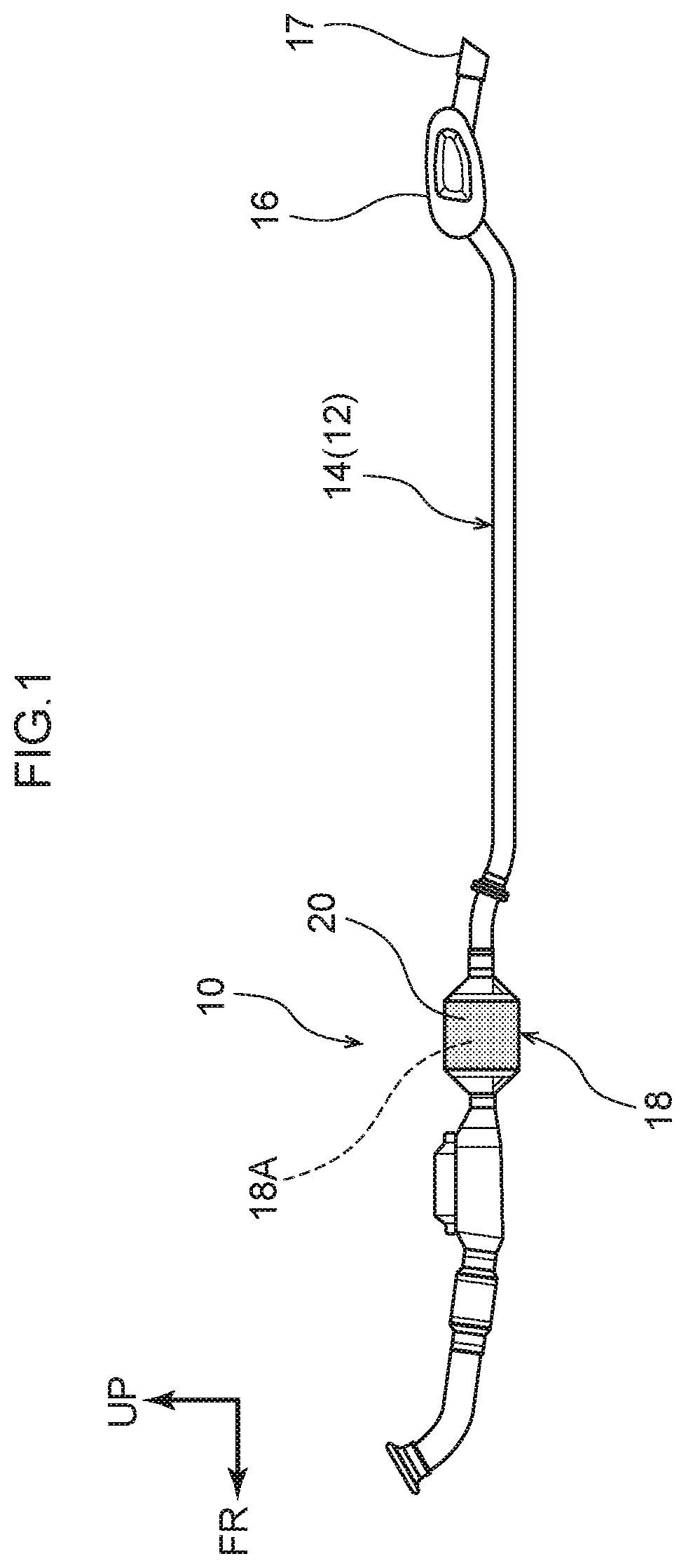
[0021]A pipe structure 10 according to the present exemplary embodiment can be excellently employed at an exhaust pipe 14 (of a vehicle), which serves as an example of a pipe 12. Below, descriptions are given using the exhaust pipe 14 of the vehicle as an example. For convenience of description, the arrow UP shown in FIG. 1 indicates a vehicle upper direction and the arrow FR indicates a vehicle front direction.

[0022]As shown in FIG. 1, the exhaust pipe 14 is provided at a lower portion of the vehicle (which is not shown in the drawings). The exhaust pipe 14 extends toward the vehicle rear side from an engine (not shown in the drawings) disposed at the vehicle front side. The exhaust pipe 14 is disposed in a state of contact with the atmosphere. A muffler 16 that constitutes a portion of the exhaust pipe 14 is connected in fluid communication with a rear end port...


PUM

PropertyMeasurementUnit
temperatureaaaaaaaaaa
timeaaaaaaaaaa
surface areaaaaaaaaaaa

Abstract

A pipe structure includes a pipe disposed in a state of contact with the air, a fluid with a temperature of at least 100° C. flowing inside the pipe; and a coating material containing nickel oxide and coated onto an outer periphery portion of the pipe.

Description

CROSS-REFERENCE TO RELATED APPLICATION[0001]This application claims priority under 35 USC 119 from Japanese Patent Application No. 2018-131084 filed Jul. 10, 2018, the disclosure of which is incorporated by reference herein in its entirety.BACKGROUNDTechnical Field[0002]The present disclosure relates to a pipe structure.Related Art[0003]Since heretofore, the use of a catalyst in which iridium, neodymium and nickel are together carried on a carrier formed of silicon carbide to clean exhaust gas from an internal combustion engine of a car or the like has been known (for example, see Japanese Patent Application Laid-Open (JP-A) No. H8-71422).SUMMARY[0004]However, although this catalyst may clean exhaust gas, it may not remove hazardous components in air (such as ozone).[0005]Accordingly, the present disclosure provides a pipe structure that may remove ozone from the air in a vicinity of a pipe.[0006]In order to achieve the object described above, a pipe structure according to a first a...

Claims


Application Information

Patent Timeline
Patent Type & Authority Patents(United States)
IPC IPC(8): F01N13/14C23C24/08F01N13/08
CPCF01N13/141C23C24/085F01N13/08F01N2260/08F01N2530/26F01N2510/00F01N2510/06F01N1/00
Inventor MURATA, TOSHIOSHINPO, YOSHIKAZU
Owner TOYOTA JIDOSHA KK
Why Eureka
Try Eureka