Power tool with reciprocating blade

a technology of power tools and blades, applied in the field of power tools, can solve the problems of more difficult control during use, and achieve the effect of improving the control efficiency of the blades

Inactive Publication Date: 2012-08-02
TECHTRONIC POWER TOOLS TECHNOLOGY LTD
View PDF3 Cites 35 Cited by
  • Summary
  • Abstract
  • Description
  • Claims
  • Application Information

AI Technical Summary

Problems solved by technology

As the height of the jig saw increases, the more difficult it is to control during use.

Method used


Image

  • Power tool with reciprocating blade
  • Power tool with reciprocating blade
  • Power tool with reciprocating blade

Examples


Embodiment Construction

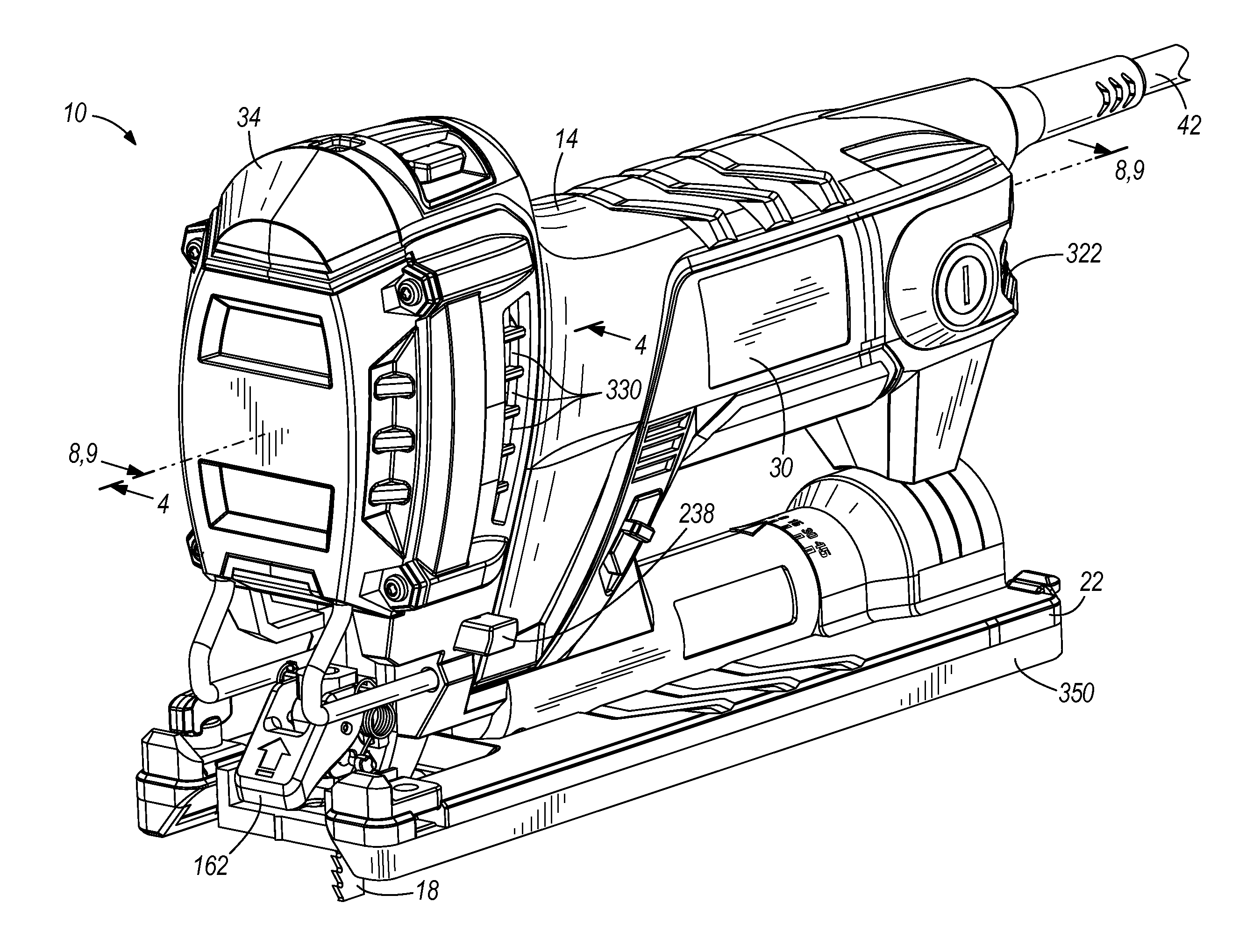
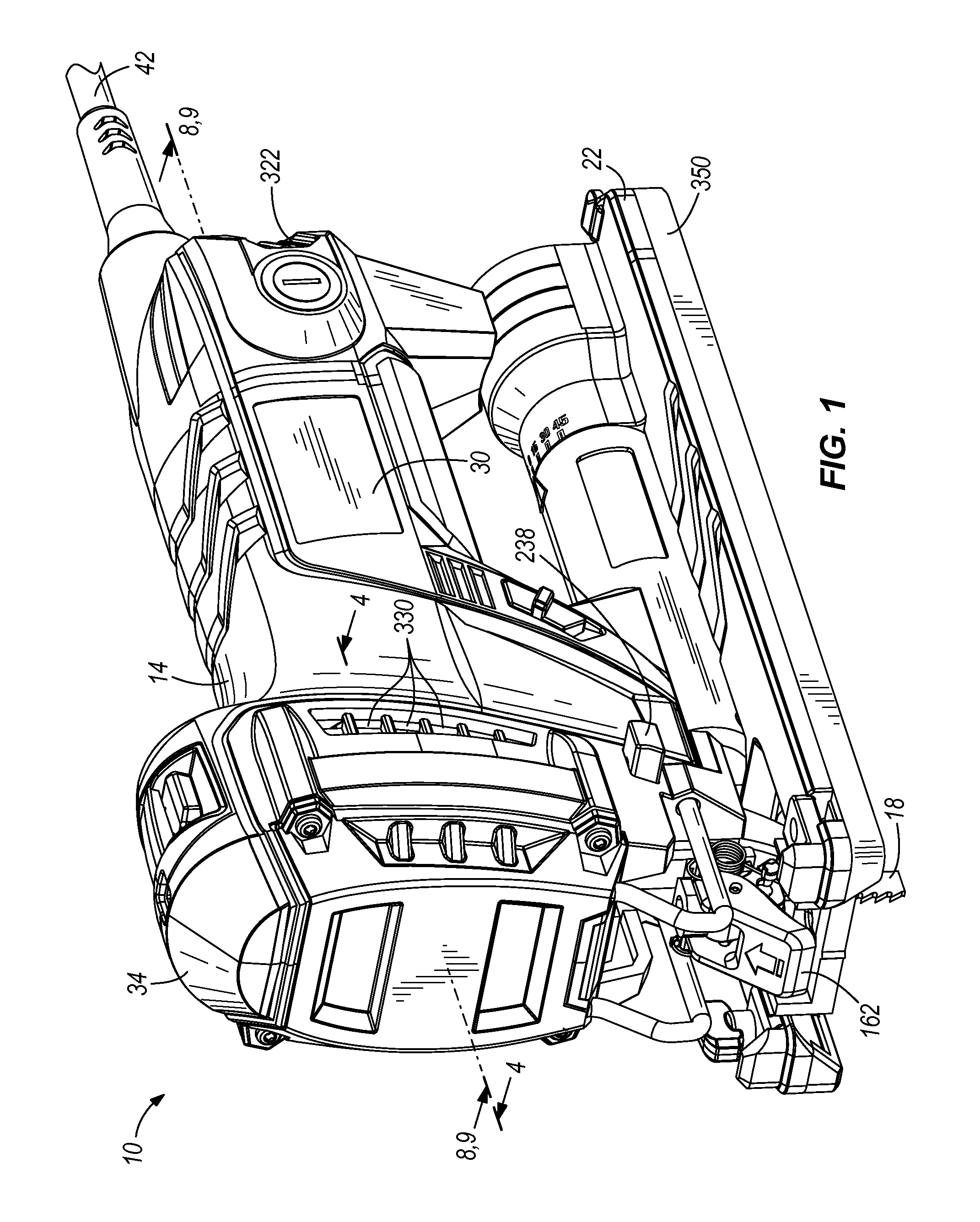
[0018]FIG. 1 illustrates a power tool, configured as a jig saw 10, embodying the invention. The jig saw 10 includes a housing 14, a reciprocating saw blade 18 proximate the front of the housing 14, and a base 22 pivotably coupled to the housing 14 to permit adjustment of the cutting angle or the bevel angle of the saw blade 18 relative to the base 22 and an underlying workpiece 26 (FIGS. 8 and 9). The housing 14 includes an elongated body portion 30 (FIG. 1) and a head 34 that defines the front end of the jig saw 10 with respect to the cutting direction along the workpiece 26. As is discussed in detail below, the elongated body portion 30 is grasped by a user of the jig saw 10 during a cutting operation. As a result, the user's hand is maintained in close proximity to the workpiece 26, which enhances the user's control over the jig saw 10 while cutting the workpiece 26.

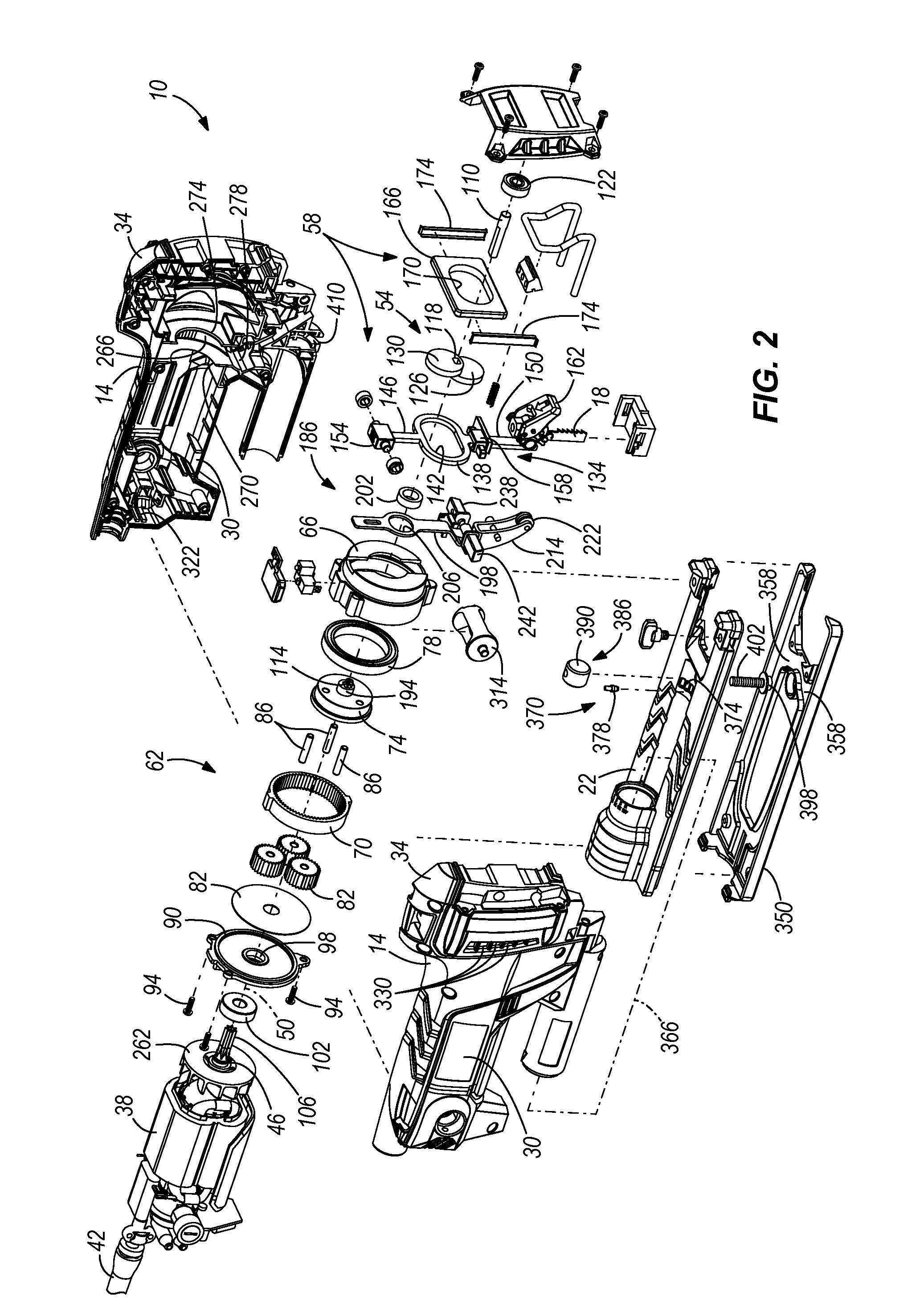
[0019]With reference to FIG. 2, the jig saw 10 also includes an electric motor 38 positioned in the elongated body ...


PUM

PropertyMeasurementUnit
bevel anglesaaaaaaaaaa
rotationaaaaaaaaaa

Abstract

A power tool includes a housing, a motor supported by the housing and having an output shaft, a planetary transmission coupled to the output shaft and having an output carrier, a dual-eccentric scotch yoke mechanism coupled to the output carrier and drivable by the planetary transmission in response to rotation of the output shaft, and a blade coupled to the dual-eccentric scotch yoke mechanism for movement in a reciprocating manner.

Description

FIELD OF THE INVENTION[0001]The present invention relates to power tools, and more particularly to jig sawsBACKGROUND OF THE INVENTION[0002]Jig saws typically include an electric motor, a blade coupled to a scotch-yoke mechanism, and a transmission including a plurality of spur gears for transferring torque from the motor to the scotch-yoke mechanism. To achieve a desired speed reduction and corresponding increase in torque, several stages of gear reduction are often employed in the transmission. Generally, as the number of stages of gear reduction in the transmission increases, the height of the jig saw must also increase to accommodate all of the spur gears in the gear train. As the height of the jig saw increases, the more difficult it is to control during use. As a result, jig saws typically include a separate handle, extending from the motor housing, that is grasped by a user to guide the saw during a cutting operation.SUMMARY OF THE INVENTION[0003]The present invention provide...

Claims


Application Information

Patent Timeline
Patent Type & Authority Applications(United States)
IPC IPC(8): B23D49/16B23D51/00
CPCB23D49/165B23D59/006B23D51/16
Inventor JERABEK, JESSE J.PAREL, THOMASMCCURRY, RONALD C.OHI, TAKUHARRISON, RYANWATSON, ELTON L.
Owner TECHTRONIC POWER TOOLS TECHNOLOGY LTD
Why Eureka
Try Eureka