

Multifunctional Hand Tool Having Continuity Tester
a multi-functional, tester technology, applied in the field of hand tools, can solve the problems of limited testing functions, bulky, easily broken, and high cost of most available continuity testers, and the bulky and easily-breakable aspects of most continuity testers do not lend themselves well to professional lighting professionals, especially those in the entertainment industry
- Summary
- Abstract
- Description
- Claims
- Application Information
AI Technical Summary
Problems solved by technology
Method used
Image

Examples
Embodiment Construction
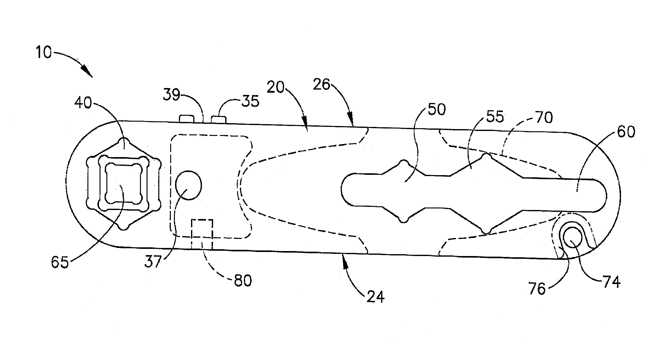
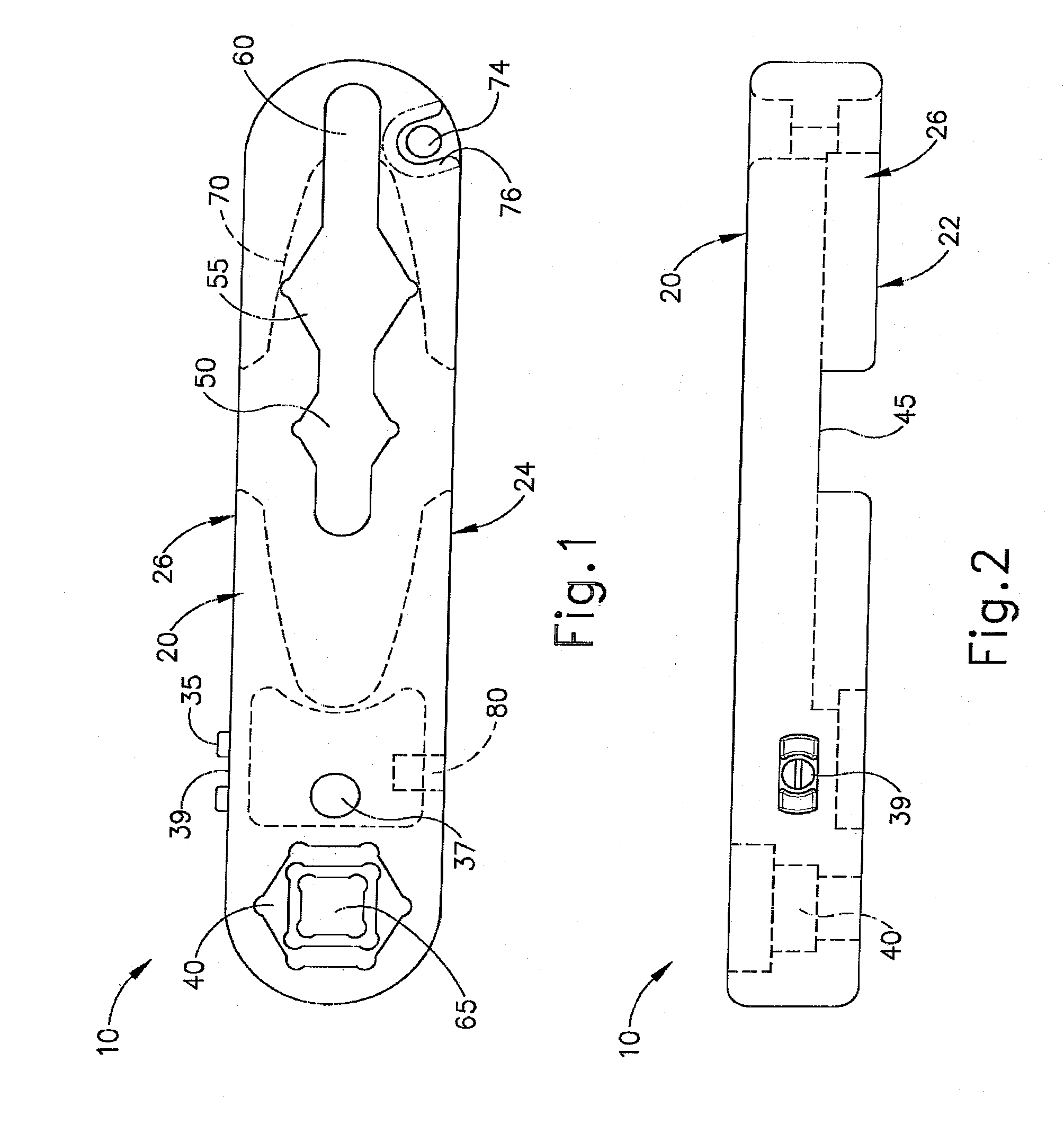
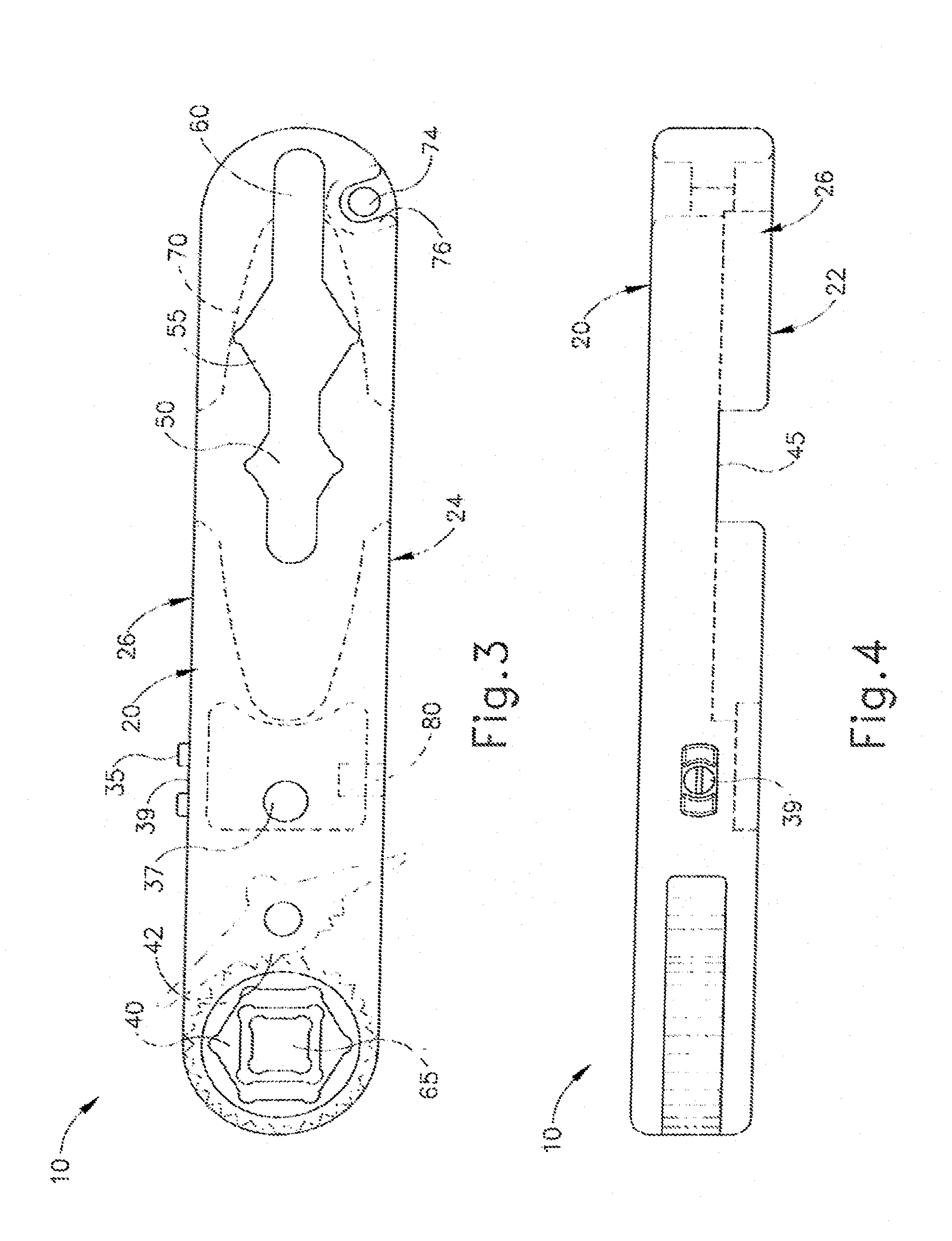
[0047]FIGS. 1-4 illustrate exemplary embodiments of a multifunctional hand tool 10 according to the present invention.
[0048]The multifunctional hand tool is comprised of a substantially planar body having a top-side 20, a bottom-side 22, a left-side 24, and a right-side 26.
[0049]In a preferred embodiment, the multifunctional hand tool is comprised of a metal, an alloy, or another electric-conducting material. In a more preferred embodiment, the multifunctional hand tool is comprised of aluminum, preferably with a hard coat anodization.
[0050]The multifunctional hand tool includes a continuity tester. The continuity tester consists of an indicator means 37 arranged in series with a power means and a single test lead 39, and the indicator means is shielded by a guard 35 on each side. In exemplary embodiments the indicator means is a light emitting diode (LED). In other exemplary embodiments, the indicator means may be an auditory signal. The power means of the exemplary embodiments may...
PUM
 Abstract
Description
Claims
Application Information