

Substrate holding device
a technology of holding device and substrate, which is applied in the direction of manufacturing tools, basic electric elements, electric devices, etc., can solve the problems of increasing manufacturing costs, and achieve the effect of stabilizing
- Summary
- Abstract
- Description
- Claims
- Application Information
AI Technical Summary
Benefits of technology
Problems solved by technology
Method used
Image

Examples
first embodiment
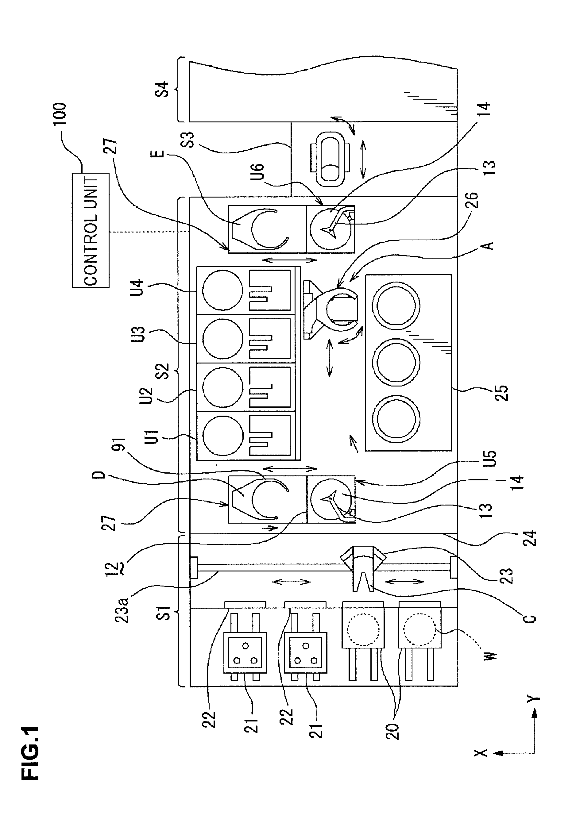
[0027]Near the center of the treatment block S2, a transfer area for the wafer W is formed. In the transfer area, a substrate transfer device 26 for delivering the wafer between all of the modules (a place where the wafer W is placed) in the DEV layer, for example, the treatment units in the shelf units U1 to U4, the developing unit 25, and the units in the shelf units U5, U6 is provided. The substrate transfer device 26 is composed of a substrate holding device (a main arm A) holding the wafer W according to the present invention, a not-illustrated driving device for configuring the main arm A to be movable in horizontal X- and Y-directions and in a vertical Z-direction and rotatable and movable around the vertical axis, a rail and so on. The driving device is drive-controlled based on a transfer program by a control unit 100.
[0028]Note that the substrate transfer device 26 is provided also in the other blocks stacked in the vertical direction as in the above-described developing t...
second embodiment
[0029]On the carrier block S1 side in the treatment block S2, the shelf unit U5 is provided at a position to which the transfer arm C and the main arm A can access as illustrated in FIG. 1, and a substrate transfer device 27 for delivering the wafer W between the units stacked in the shelf unit 5 is provided. The substrate transfer device 27 is composed of a substrate holding device (a delivery arm D) holding the wafer W according to the present invention, a not-illustrated driving device for configuring the delivery arm D to be movable in horizontal X- and Y-directions and in a vertical Z-direction and rotatable and movable around the vertical axis, a rail and so on. The driving device is drive-controlled based on a transfer program by the control unit 100.
[0030]In this case, the shelf unit U5 includes the not-illustrate delivery stage in order to deliver the wafer W to / from the main arm A. Further, the shelf unit U5 includes a plurality of partitioned housing blocks (not illustrat...
third embodiment
[0031]On the other hand, on the interface blocks S3 side in the treatment block S2, the shelf unit U6 is provided at a position to which the main arm A can access, and a substrate transfer device 27 for delivering the wafer W between the units constituting the shelf unit U6 is provided. The substrate transfer device 27 is composed of a substrate holding device (a delivery arm E) holding the wafer W according to the present invention, a not-illustrated driving device for configuring the delivery arm E to be movable in horizontal X- and Y-directions and in a vertical Z-direction and rotatable and movable around the vertical axis, a rail and so on. The driving device is drive-controlled based on a transfer program by the control unit 100.
[0032]The shelf unit U6 includes, as with the shelf unit U5, a not-illustrate delivery stage in order to deliver the wafer W to / from the main arm A, a plurality of partitioned housing blocks (not illustrated), a plurality of mounting shelves 13, and a ...
PUM
 Abstract
Description
Claims
Application Information