Wireless energy transfer using repeater resonators
What is AI technical title?
AI technical title is built by Patsnap AI team. It summarizes the technical point description of the patent document.
a repeater resonator and wireless technology, applied in the direction of battery data exchange, inductance, safety/protection circuit, etc., can solve the problems of inconvenient use, inconvenient transferring of electrical energy, and inefficient power transfer
Active Publication Date: 2012-09-20
WITRICITY CORP
View PDF2 Cites 246 Cited by
Summary
Abstract
Description
Claims
Application Information
AI Technical Summary
This helps you quickly interpret patents by identifying the three key elements:
Problems solved by technology
Method used
Benefits of technology
Benefits of technology
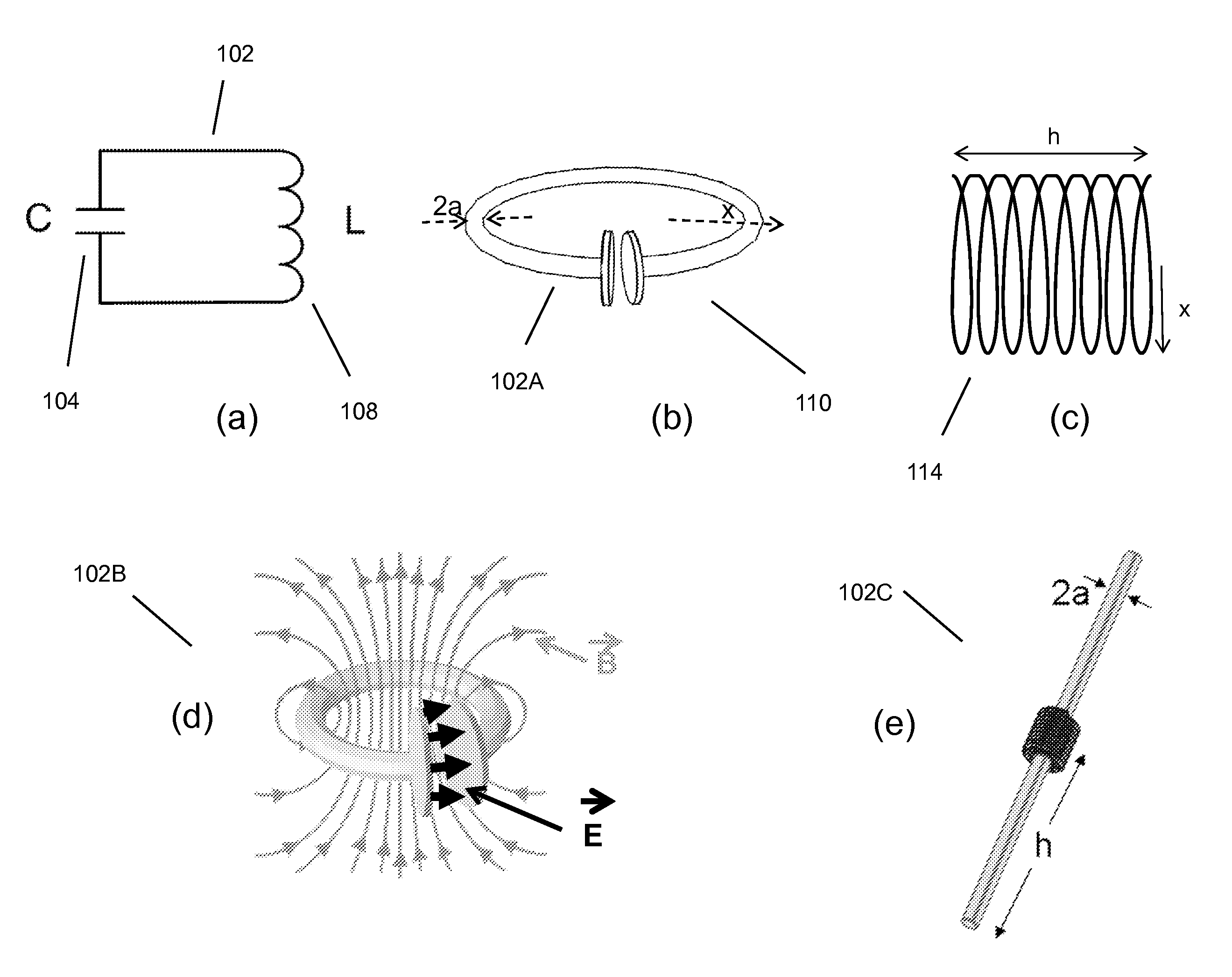
[0015]It is important to appreciate the difference between the high-Q magnetic resonator scheme disclosed here and the known close-range or proximity inductive schemes, namely, that those known schemes do not conventionally utilize high-Q resonators. Using coupled-mode theory (CMT), (see, for example, Waves and Fields in Optoelectronics, H. A. Haus, Prentice Hall, 1984), one may show that a high-Q resonator-coupling mechanism can enable orders of magnitude more efficient power delivery between resonators spaced by mid-range distances than is enabled by traditional inductive schemes. Coupled high-Q resonators have demonstrated efficient energy transfer over mid-range distances and improved efficiencies and offset tolerances in short range energy transfer applications.
Problems solved by technology
However, this type of radiative transfer is very inefficient because only a tiny portion of the supplied or radiated power, namely, that portion in the direction of, and overlapping with, the receiver is picked up.
Such inefficient power transfer may be acceptable for data transmission, but is not practical for transferring useful amounts of electrical energy for the purpose of doing work, such as for powering or charging electrical devices.
However, these directed radiation schemes may require an uninterruptible line-of-sight and potentially complicated tracking and steering mechanisms in the case of mobile transmitters and / or receivers.
In addition, such schemes may pose hazards to objects or people that cross or intersect the beam when modest to high amounts of power are being transmitted.
Method used
Image
Click on the blue label to locate the original text in one second.
Reading with bidirectional positioning of images and text.
Examples
examples
System Block Diagrams
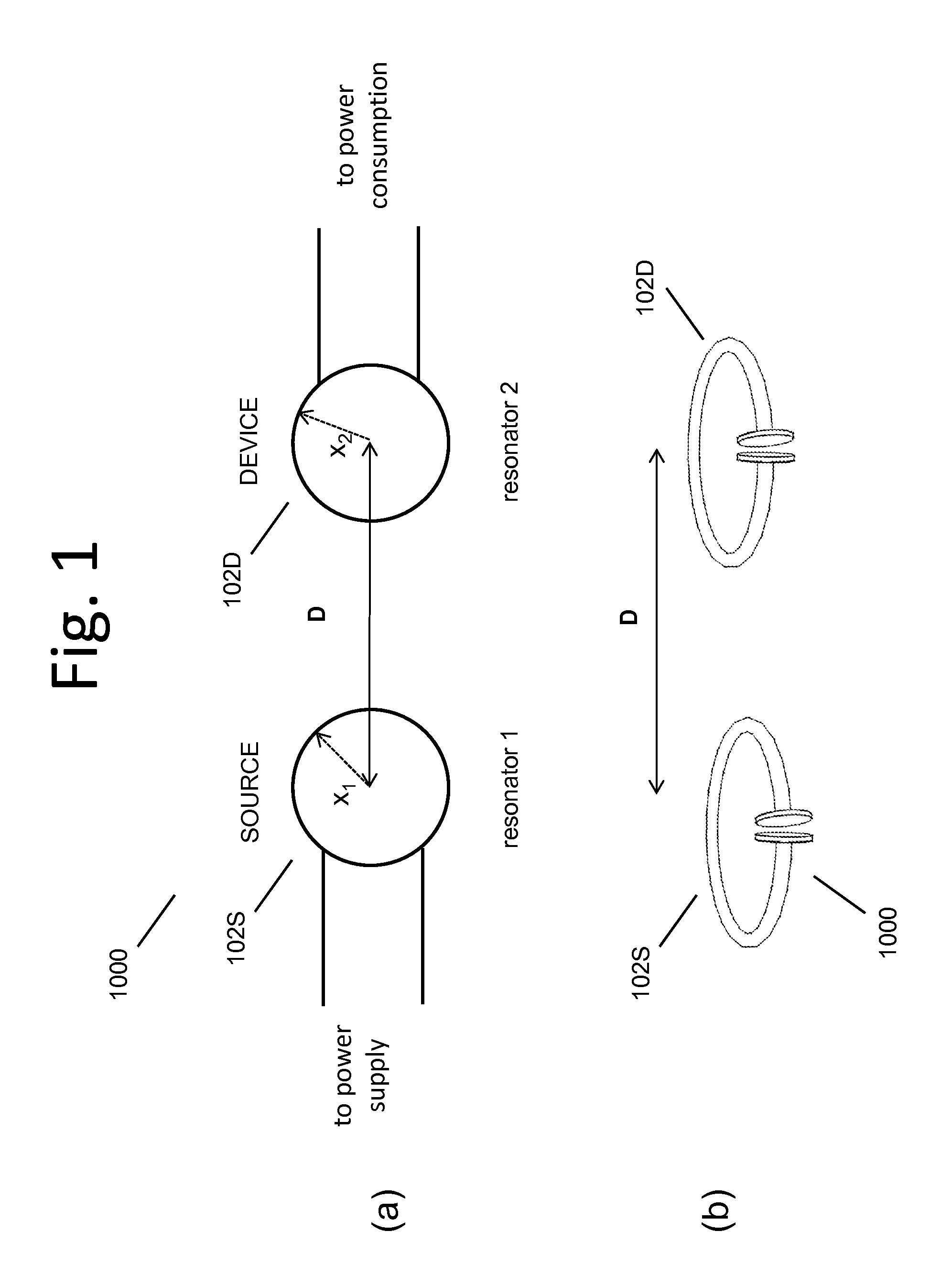
[0404]We disclose examples of high-Q resonators for wireless power transmission systems that may wirelessly power or charge devices at mid-range distances. High-Q resonator wireless power transmission systems also may wirelessly power or charge devices with magnetic resonators that are different in size, shape, composition, arrangement, and the like, from any source resonators in the system.
[0405]FIG. 1(a)(b) shows high level diagrams of two exemplary two-resonator systems. These exemplary systems each have a single source resonator 102s or 104S and a single device resonator 102D or 104D. FIG. 38 shows a high level block diagram of a system with a few more features highlighted. The wirelessly powered or charged device 2310 may include or consist of a device resonator 102D, device power and control circuitry 2304, and the like, along with the device 2308 or devices, to which either DC or AC or both AC and DC power is transferred. The energy or power source for a ...
PUM
Abstract
A bag for wireless energy transfer comprising a compartment for storing an electronic device enabled for wireless energy transfer, and at least one magnetic resonator positioned for wireless energy transfer to the electronic device, wherein a the at least one magnetic resonator optionally operates in one of three modes: (1) as a repeater resonator to extend the energy transfer to the electronic device from an external wireless energy source, (2) as a source resonator transferring energy from a battery in the bag to the electronic device, and (3) as an energy capture resonator receiving wireless energy from an external source to recharge a battery in the bag.
Description
CROSS-REFERENCE TO RELATED APPLICATIONS[0001]This application is a continuation of U.S. application Ser. No. 12 / 759,047 filed Apr. 13, 2010.[0002]The Ser. No. 12 / 759,047 application is a continuation-in-part of U.S. application Ser. No. 12 / 757,716 filed Apr. 9, 2010.[0003]The Ser. No. 12 / 757,716 application is a continuation-in-part of U.S. application Ser. No. 12 / 749,571 filed Mar. 30, 2010, which is a continuation-in-part of the following U.S. Applications: U.S. application Ser. No. 12 / 639,489 filed Dec. 16, 2009; and U.S. application Ser. No. 12 / 647,705 filed Dec. 28, 2009.[0004]The Ser. No. 12 / 749,571 application a continuation-in-part of U.S. application Ser. No. 12 / 567,716 filed Sep. 25, 2009, which claims the benefit of the following U.S. patent applications: U.S. App. No. 61 / 100,721 filed Sep. 27, 2008; U.S. App. No. 61 / 108,743 filed Oct. 27, 2008; U.S. App. No. 61 / 147,386 filed Jan. 26, 2009; U.S. App. No. 61 / 152,086 filed Feb. 12, 2009; U.S. App. No. 61 / 178,508 filed May 1...
Claims
Application Information
Patent Timeline
Application Date:The date an application was filed.
Publication Date:The date a patent or application was officially published.
First Publication Date:The earliest publication date of a patent with the same application number.
Issue Date:Publication date of the patent grant document.
PCT Entry Date:The Entry date of PCT National Phase.
Estimated Expiry Date:The statutory expiry date of a patent right according to the Patent Law, and it is the longest term of protection that the patent right can achieve without the termination of the patent right due to other reasons(Term extension factor has been taken into account ).
Invalid Date:Actual expiry date is based on effective date or publication date of legal transaction data of invalid patent.
Patent Type & AuthorityApplications(United States)

