Selectively expandable operative element support structure and methods of use

a technology of operative elements and support structures, applied in the field of selective expansion of operative element support structures and methods of use, devices and techniques for providing tissue therapy, can solve the problems of additional challenges, hindering the ability to properly position instruments to provide treatment to tissue sites, etc., and achieves the effect of small expansion index

Active Publication Date: 2012-09-20
TYCO HEALTHCARE GRP LP
View PDF44 Cites 31 Cited by
  • Summary
  • Abstract
  • Description
  • Claims
  • Application Information

AI Technical Summary

Benefits of technology

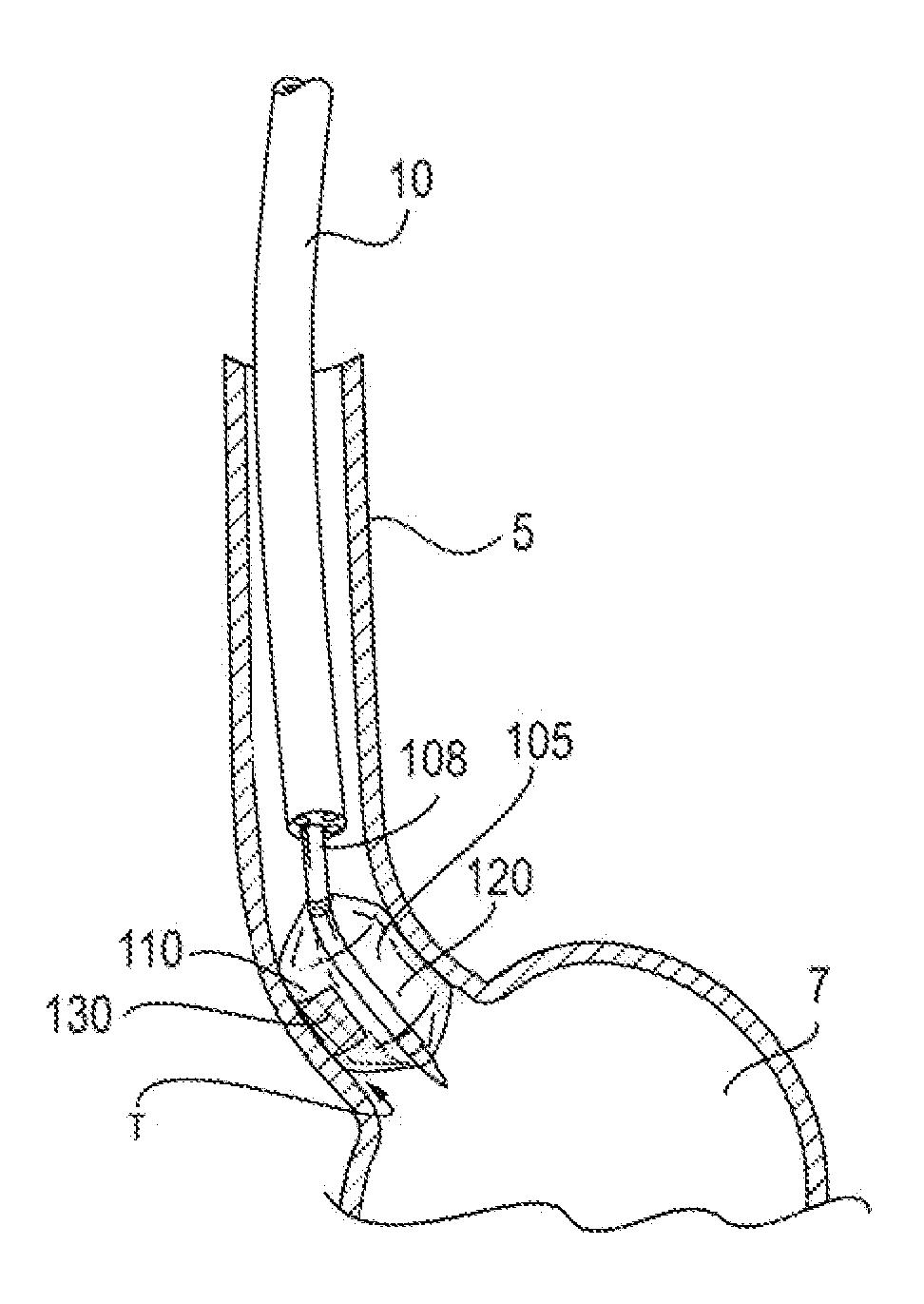
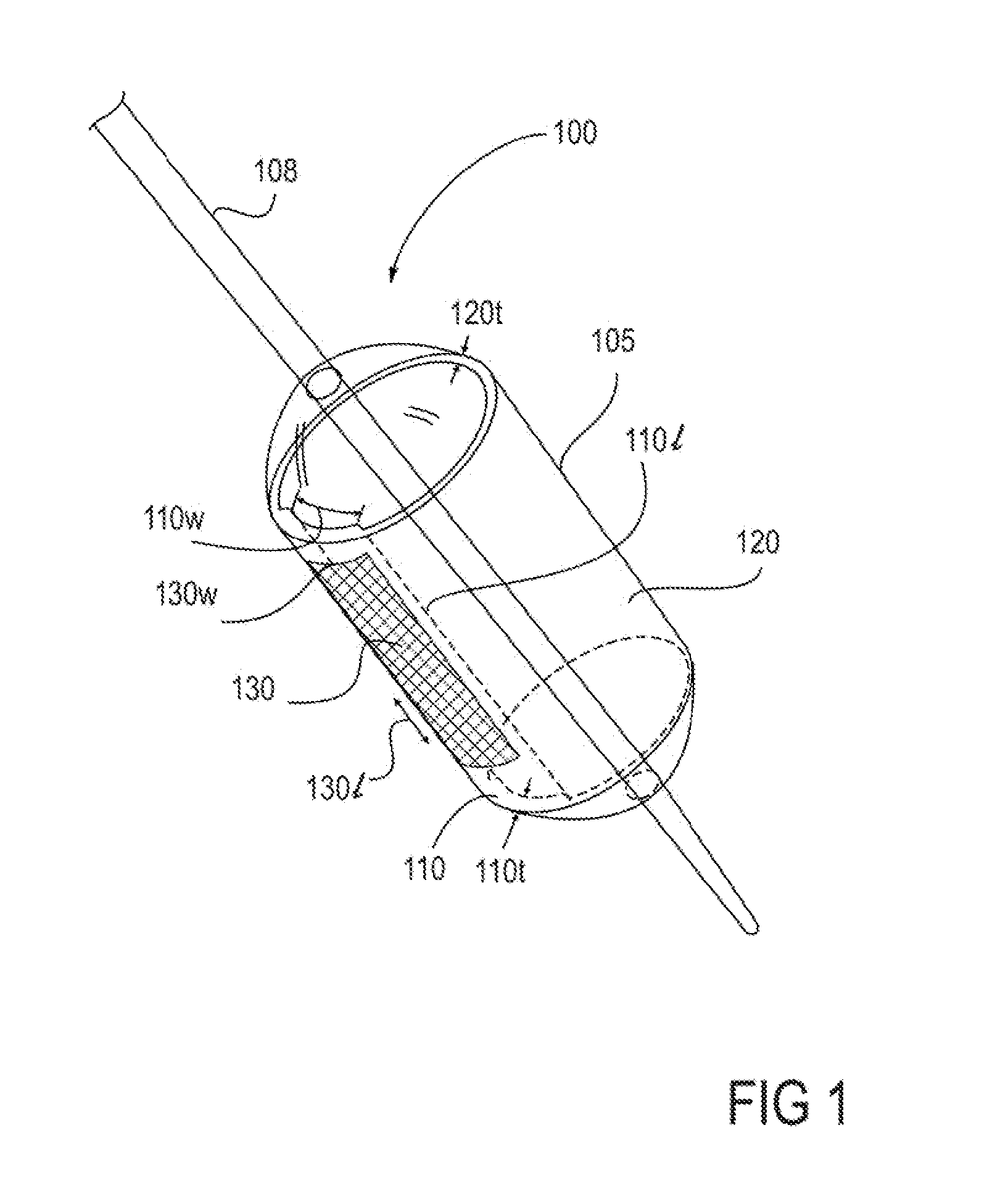
[0004]In one embodiment of the present invention, there is provided a device having an expandable support member having a first portion and a second portion. The first portion is adapted to have a smaller expansion index than the second portion. An operative element is supported at least in part by the expandable support member. The operative element may be a therapeutic or diagnostic instrument. In various embodiments, the operative element is supported in whole or in part by the first portion. In various embodiments, the operative element is supported in part by the second portion. In one aspect, the surface area of the ex

Problems solved by technology

Currently, the ability to properly position an instrument to provide treatment to a tissue site may be hindered by the location

Method used


Image

  • Selectively expandable operative element support structure and methods of use
  • Selectively expandable operative element support structure and methods of use
  • Selectively expandable operative element support structure and methods of use

Examples


example 1

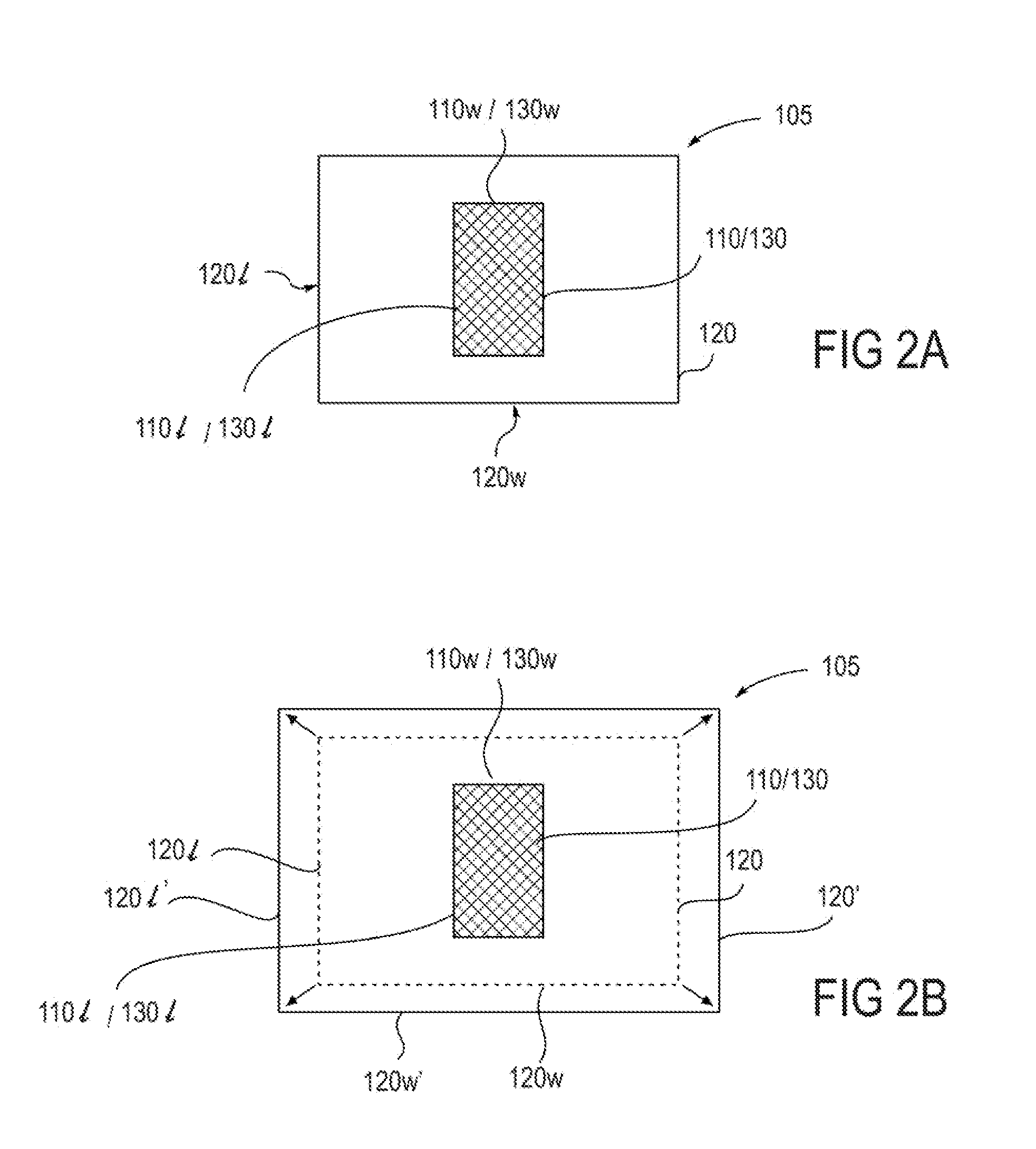
[0085]The exemplary body lumen has circumference of about a 60 mm. A device (such as an ablational structure) encompassing an arc or a circumferential span of 40 mm arc is mounted on a comparably sized first portion of an expandable support member. In this example, when the 40 mm device is in position to provide therapy, the expandable support member second portion would be expanded to fill out the remaining 20 mm in lumen circumference. Thus, when the expandable support member is positioned for use in the lumen and the second portion of the expandable support member is expanded, the second portion has a smaller area than the first portion.

example 2

[0086]The exemplary body lumen has a circumference of about 120 mm. A device such as an ablational structure encompassing an arc or a circumferential span of 40 mm is mounted on a comparably sized expandable support member first portion. Prior to positioning the device for use, the expandable support member second portion has a smaller area than the expandable support member first portion. However, when the expandable support member is expanded and is in position for use, the expandable support member second portion would be expanded to cover the remaining 80 mm in lumen circumference. Thus, when the expandable support member is positioned for use in the lumen and the second portion is expanded, the expandable support member second portion has a larger area than the expandable support member first portion.


PUM


Abstract

In one embodiment, a device is provided including an expandable support member having a first portion and a second portion is provided. The first portion is adapted to have a smaller expansion index than the second portion. A therapeutic or diagnostic instrument is supported, at least in part, by the expandable support member first portion. In another embodiment, the support member is adapted for non-uniform expansion of the first and second portions. There are also described methods of forming therapeutic devices. There are also described methods of providing therapy to tissue in a body by positioning a device in proximity to tissue in a body selected to receive therapy. Next, the expandable support member second portion is expanded until the instrument is at a therapeutic position relative to the tissue in a body selected to receive therapy. Thereafter, therapy or diagnosis is provided to the selected tissue using the device.

Description

INCORPORATION BY REFERENCE[0001]All publications, patents, and patent applications mentioned in this specification are herein incorporated in their entirety by reference for all purposes to the same extent as if each individual was specifically and individually indicated to be incorporated by reference.FIELD OF THE INVENTION[0002]This application is related to the devices and techniques of providing therapy to tissue. More particularly, the invention relates to ablating target tissue in the gastrointestinal tract with radiofrequency energy.BACKGROUND OF THE INVENTION[0003]The present invention relates devices and techniques for providing therapy to tissue. Currently, the ability to properly position an instrument to provide treatment to a tissue site may be hindered by the location of that treatment site within the body. Additional challenges may arise by the anatomical variation or makeup of the tissue site. As a result, there is a need for diagnostic or therapeutic instruments ada...

Claims


Application Information

Patent Timeline
IPC IPC(8): A61B18/18A61M29/00
CPCA61B18/1492A61B2018/0016A61B2018/1497A61N7/022A61B18/06A61B2018/1861A61B18/24A61B2018/0022A61B2018/00488A61B2018/00577A61B2018/0212A61B18/082
Inventor WALLACE, MICHAEL P.GARABEDIAN, ROBERTUTLEY, DAVID S.GERBERDING, BRENT C.DE CSEPEL, JOHN
Owner TYCO HEALTHCARE GRP LP
Why Eureka
Try Eureka