Locking differential assembly

a differential and locking technology, applied in mechanical equipment, transportation and packaging, gearing, etc., can solve the problems of less desirable, less engagement between the side gear and the locking ring, and sacrifice torque or traction

Inactive Publication Date: 2012-09-27
RING & PINION SERVICE
View PDF6 Cites 18 Cited by
  • Summary
  • Abstract
  • Description
  • Claims
  • Application Information

AI Technical Summary

Problems solved by technology

While this differential action is desirable in many driving conditions, it may sacrifice torque or traction in some environments and is therefore less desirable in those cases.
This design, however, is relatively bulky and provides less engagement between the side gear and the locking ring than may be desired.
The locking ring also includes internal and external splines or teeth and other aspects that complicate the design or make it less than desirable.
Nonetheless, merely reversing the positions of the air chamber and return spring does not overcome some of the other defects in the design.
In addition, the inclusion of interior and exterior splines or teeth on the lock ring are less than desirable, and the overall design leads to a short distance of travel for the locking ring, further contributing to these concerns.

Method used


Image

  • Locking differential assembly
  • Locking differential assembly
  • Locking differential assembly

Examples


Embodiment Construction

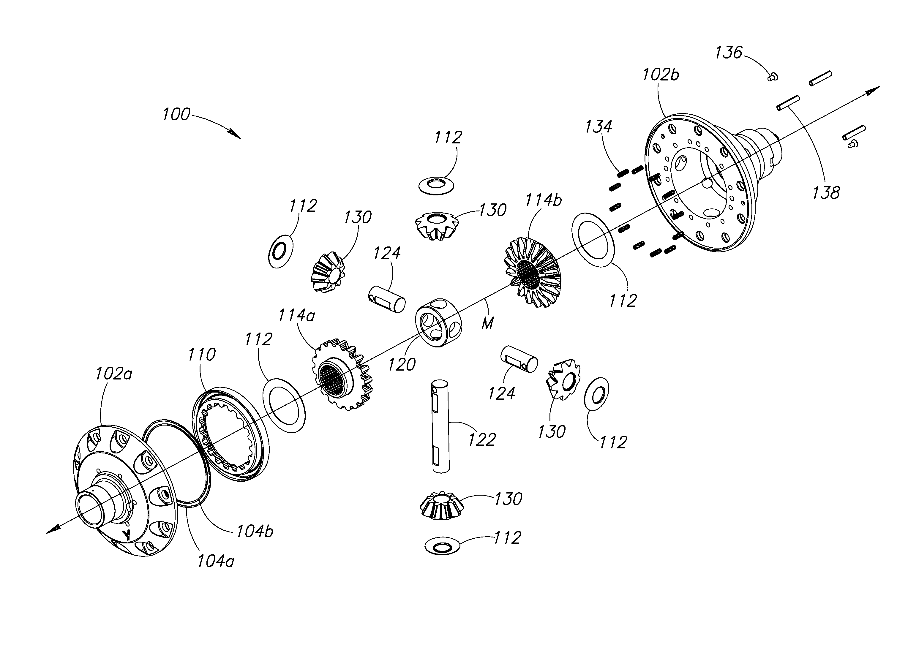
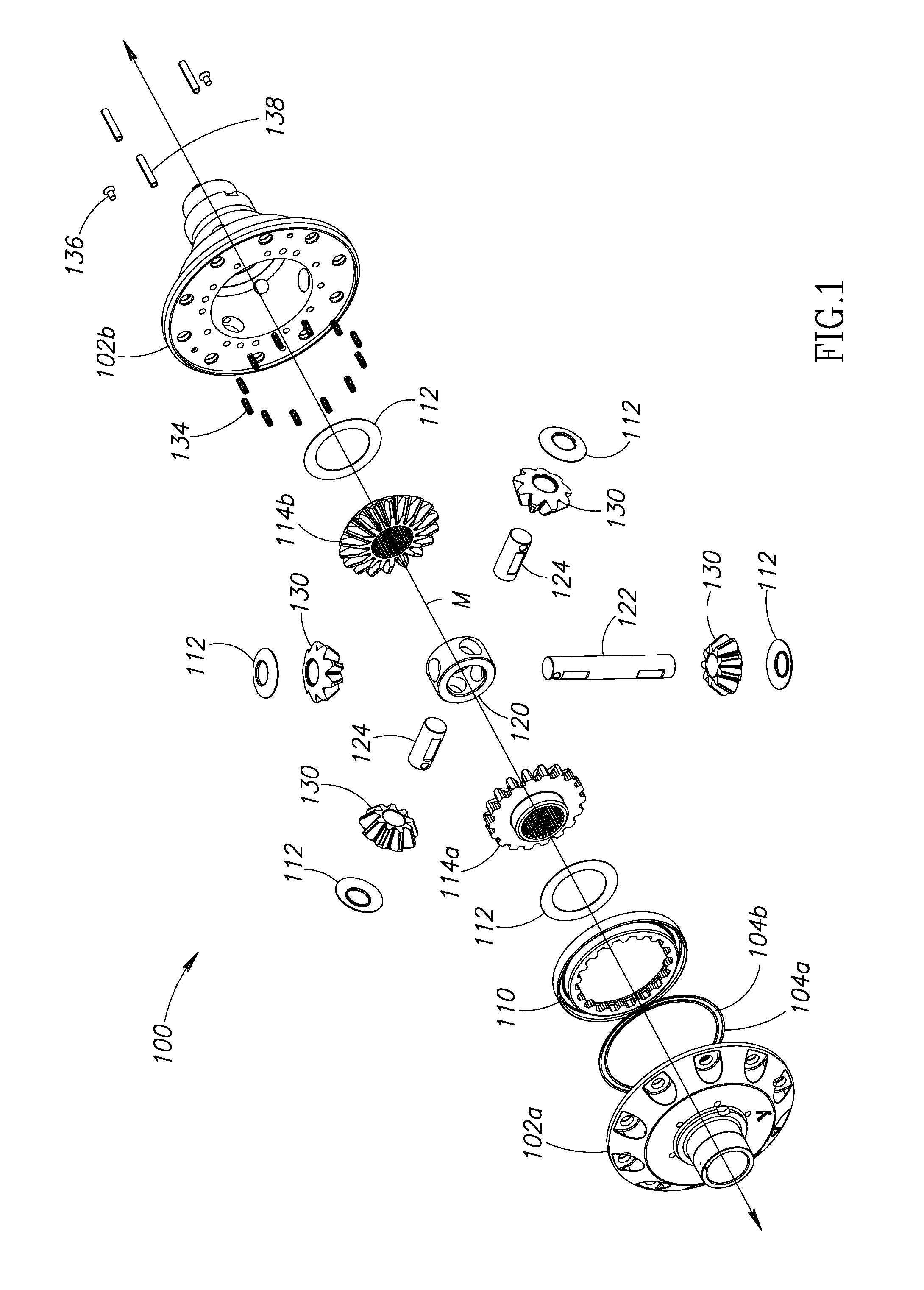
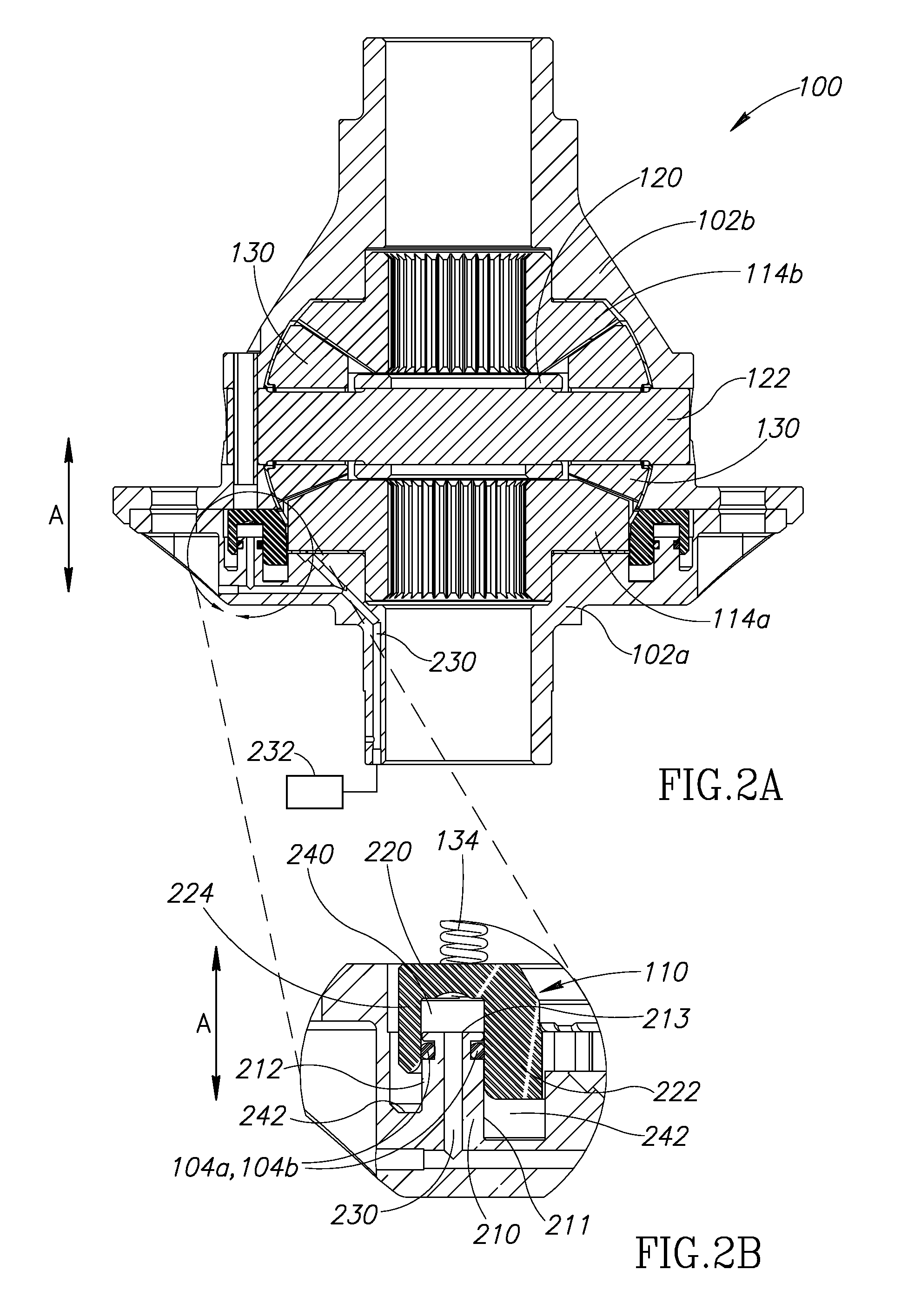
[0016]FIG. 1 is an exploded view of a locking differential assembly 100 according to preferred aspects of the present invention. The assembly 100 includes a main housing 102a and a housing cover 102b that support and house components of the assembly 100. Half axles are preferably splined to bevel gears, or side gears, for rotation along a major axis M. In general, the cover and housing may be referred to collectively as the housing or carrier. The differential assembly 100 includes a first side gear 114a and a second side gear 114b opposite the first side gear 114a. The side gears rotate about the major axis.

[0017]The assembly 100 also includes a number of pinion gears 130 (four shown in the example of FIG. 1, but either more or fewer may be used) arranged to mesh with the first and second side gears 114a, 114b. Each pinion gear 130 is engaged with both the first and second side gears 114a, 114b.

[0018]The assembly 100 can also include a spider block 120, a long cross shaft 122 and ...


PUM


Abstract

A locking differential having a movable locking ring that can selectively engage a gear of the differential to lock or unlock the differential is disclosed. The locking ring is moved by a pressure source, such as a pneumatic pressure source, and a spring. The locking ring engages a fixed annular ring in the case of the differential. Two O-rings create a seal between sides of the fixed annular ring and arms of the locking differential.

Description

PRIORITY CLAIM[0001]This application claims the benefit of U.S. provisional application No. 61 / 454,880, filed Mar. 21, 2011.FIELD OF THE INVENTION[0002]The present invention relates generally to a selectively lockable differential having a locking ring that engages a gear of the differential to lock the differential.BACKGROUND OF THE INVENTION[0003]Automotive differentials are useful in transferring the rotational force from a driveshaft to the driving wheels of the vehicle. In automobiles and other vehicles, the differential allows the right and left wheels of the vehicle to rotate at different rates. When a vehicle turns, the outer wheels have a greater distance to travel due to the larger radius of the turn. Differentials allow this to happen without skidding, slipping, or over-running either of the wheels. While this differential action is desirable in many driving conditions, it may sacrifice torque or traction in some environments and is therefore less desirable in those cases...

Claims


Application Information

Patent Timeline
Patent Type & Authority Applications(United States)
IPC IPC(8): F16H48/24
CPCF16H48/08F16H48/32F16H48/24
Inventor HAUGEBERG, BRYAN
Owner RING & PINION SERVICE
Why Eureka
Try Eureka