Differential magnetic field sensor structure for orientation independent measurement

a sensor structure and magnetic field technology, applied in the field of magnetic field sensors, can solve problems such as applications that cannot control the sensor-to-target alignmen

Active Publication Date: 2012-10-04
ALLEGRO MICROSYSTEMS INC
View PDF9 Cites 70 Cited by
  • Summary
  • Abstract
  • Description
  • Claims
  • Application Information

AI Technical Summary

Benefits of technology

[0009]Embodiments of the invention may include one or more of the following features. The circuitry can include circuitry to produce a first differential signal associated with the first differential channel and a second differential signal associated with the second differential channel, and the circuitry can further include a differential signal generator to receive as inputs the first and second differential signals and to produce as an output the single differential signal. The first and second differential signals will have amplitudes that are dependent on the orientation angle. Where the first differential signal has a first amplitude and the second differential signal has a second amplitude, the differential signal generator can operate to select the first differential signal as the single differential signal when an absolute value of the first amplitude is greater than an absolute value of the second amplitude and the differential signal generator can operate to select the second differential signal as the single differential signal when the absolute value of the first amplitude is not greater than the absolute value of the second amplitude. The circuitry can also include circuitry to receive as inputs a first magnetic field sensing output signal associated with the first sensing element, a second magnetic field sensing output signal associated with the second sensing element and a third magnetic field sensing output signal associated with the third sensing element. The differential signal generator can operate to produce the single differential signal by combining mathematically any two or more of the first magnetic field sensing output signal, the second magnetic field sensing output signal, the third magnetic field sensing output signal, the first differential signal and the second differential signal.

Problems solved by technology

Consequently, applications that cannot control the sensor-to-target alignment usually employ a non-differential sensing type sensor.

Method used


Image

  • Differential magnetic field sensor structure for orientation independent measurement
  • Differential magnetic field sensor structure for orientation independent measurement
  • Differential magnetic field sensor structure for orientation independent measurement

Examples


Embodiment Construction

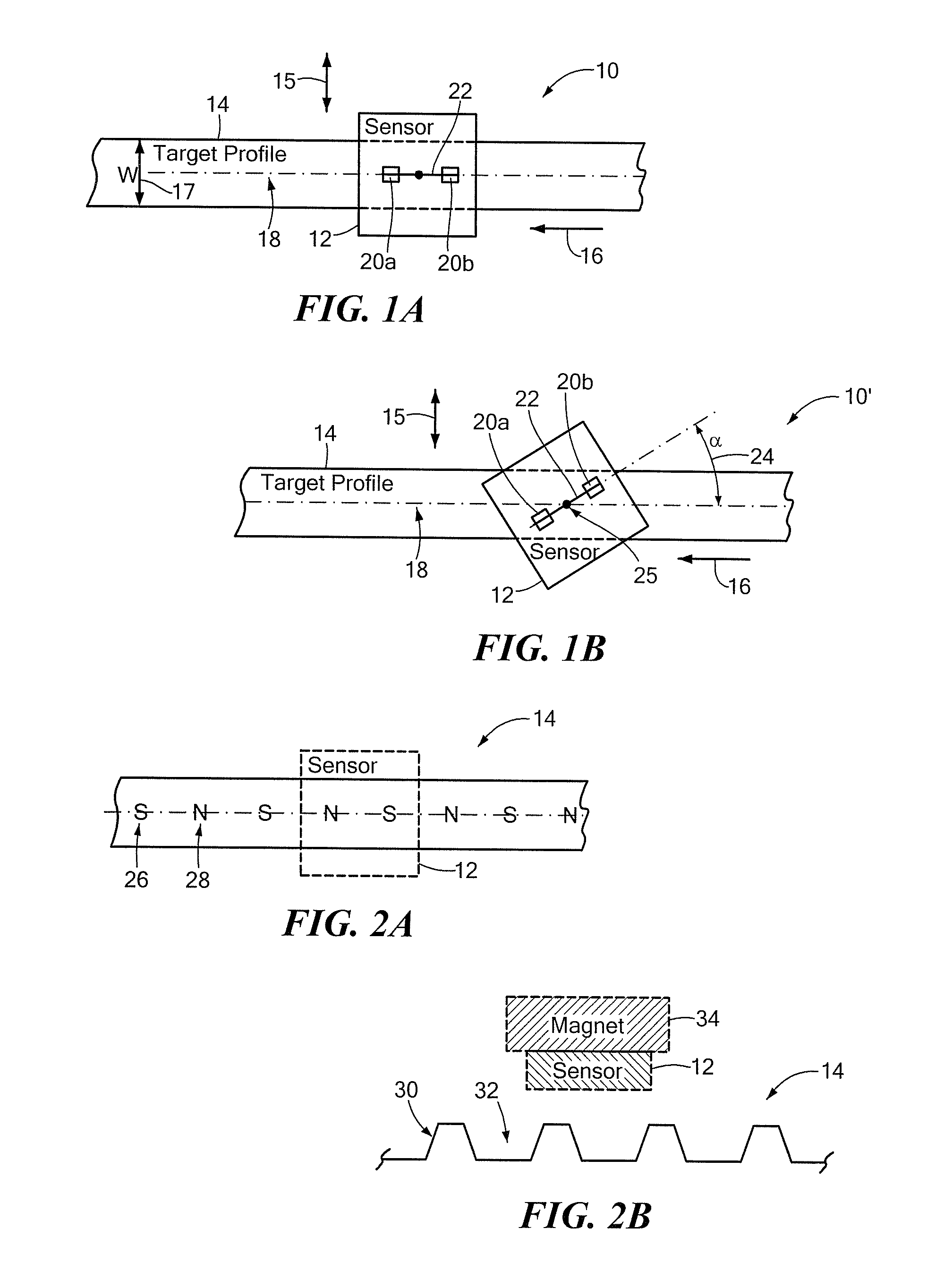
[0022]Referring to FIG. 1A, a sensing arrangement 10 in which a magnetic field sensor 12 is arranged in a radial sensing position relative to a rotating target profile 14 is shown. An axis of rotation is indicated by arrow 15. A direction of motion of the rotating target profile 14 is indicated by arrow 16. Although shown in one direction, the motion could be in the opposite direction or both directions. The target profile 14, which has a width “W”17, faces the “front” of the magnetic field sensor 12. The mid-point of the face width is indicated by a centerline 18 and referred to herein as the target profile's reference axis. The magnetic field sensor 12 is a differential sensing device and, as such, includes two sensing elements 20a and 20b for generating a differential signal responsive to change in magnetic field strength at a location relative to the target profile 14. That location corresponds to a differential channel (not shown). Associated with the differential channel is a ...


PUM


Abstract

A differential magnetic field sensor that enables operation that is independent of sensor-to-target orientation is presented. The differential magnetic field sensor is provided with at least two differential channels. Each differential channel includes a pair of magnetic field sensing elements and has a respective sensing axis defined by those magnetic field sensing elements. The sensing axes are not aligned with respect to each other. One sensing axis is positioned relative to a reference axis of a target profile to define an orientation angle between the sensing axis and the reference axis. The differential magnetic field sensor includes circuitry to produce differential signals associated with the differential channels and use those differential signals to produce a single differential signal having an amplitude that is independent of the orientation angle.

Description

CROSS-REFERENCE TO RELATED APPLICATIONS[0001]Not applicable.STATEMENT REGARDING FEDERALLY SPONSORED RESEARCH[0002]Not applicable.FIELD OF THE INVENTION[0003]This invention relates generally to magnetic field sensors and more particularly, to differential magnetic field sensors.BACKGROUND OF THE INVENTION[0004]Magnetic field sensors that sense the rotational motion of a target are known. The target can be a magnetic or ferrous target. Such sensors detect the features of the rotating target's profile, for example, teeth / valleys of a ferrous gear target or north / south poles of a magnetic target such as a ring magnet.[0005]The magnetic field associated with the target profile is sensed by a magnetic field sensing element, such as Hall element or magnetoresistive (MR) element. As the target passes the sensing element, the magnetic field experienced by the sensing element varies in relation to the target profile. The sensing element provides a signal proportional to the sensed magnetic fi...

Claims


Application Information

Patent Timeline
Patent Type & Authority Applications(United States)
IPC IPC(8): G01R33/02
CPCG01R33/0005G01R33/091G01R33/072G01R33/0029
Inventor FRIEDRICH, ANDREAS P.
Owner ALLEGRO MICROSYSTEMS INC
Why Eureka
Try Eureka