
Switching device and related switchgear

Active Publication Date: 2012-11-15
ABB (SCHWEIZ) AG +1
View PDF3 Cites 15 Cited by
  • Summary
  • Abstract
  • Description
  • Claims
  • Application Information

AI Technical Summary

Benefits of technology

The patent describes a switching device that can connect or disconnect a power line to an electrical load. The device has a housing with a movable contact that can be connected or separated from a fixed contact. The device also has an insulating support with a plurality of semiconductor devices that are connected in series and are connected to both the fixed and movable contacts. The semiconductor devices are installed into the housing to surround at least a portion of the fixed and movable contacts when they are connected. The technical effect of this design is that it allows for reliable and efficient switching of power lines with low contact resistance and high reliability.

Problems solved by technology

The large number of semiconductor devices is due to the fact that each semiconductor device cannot withstand a tension value above a certain limit operation value, for example, at about 1 kV for standard devices.

Method used


Image

  • Switching device and related switchgear
  • Switching device and related switchgear
  • Switching device and related switchgear

Examples


Embodiment Construction

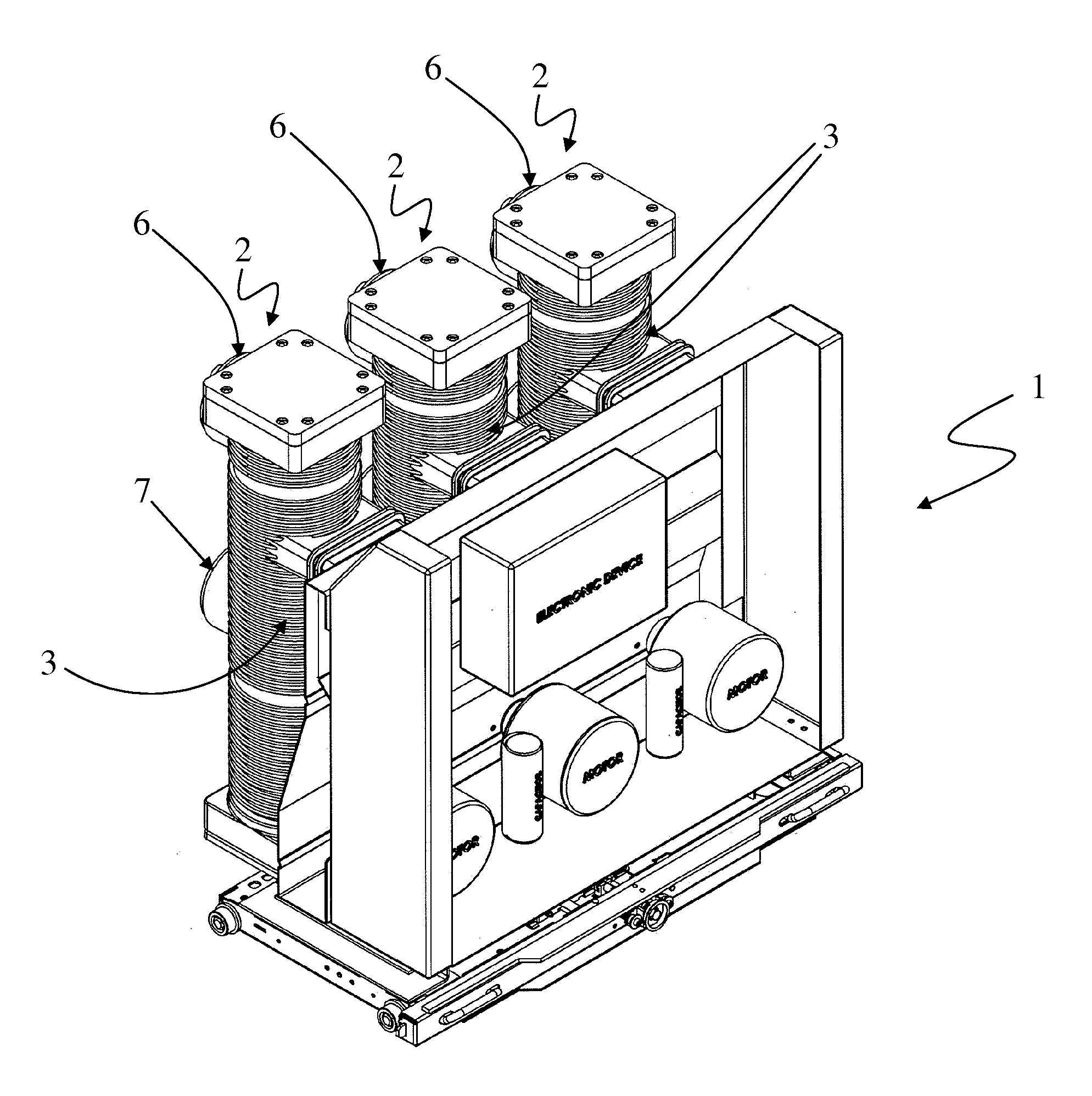
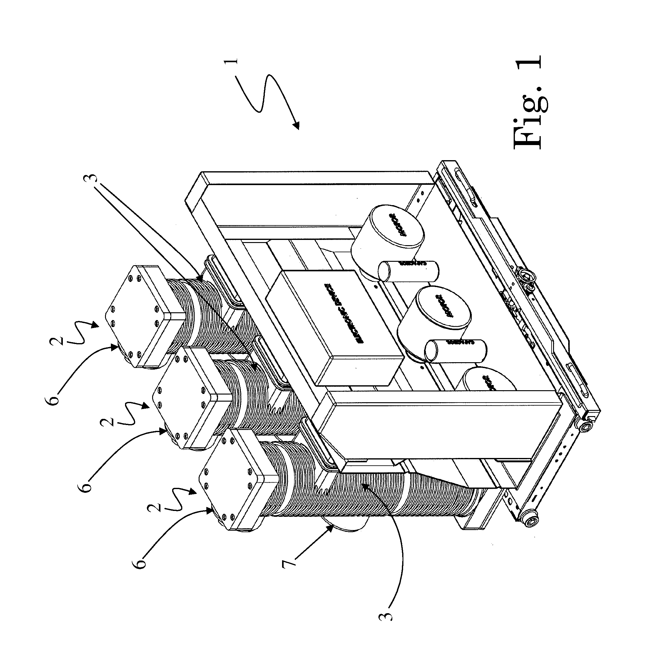
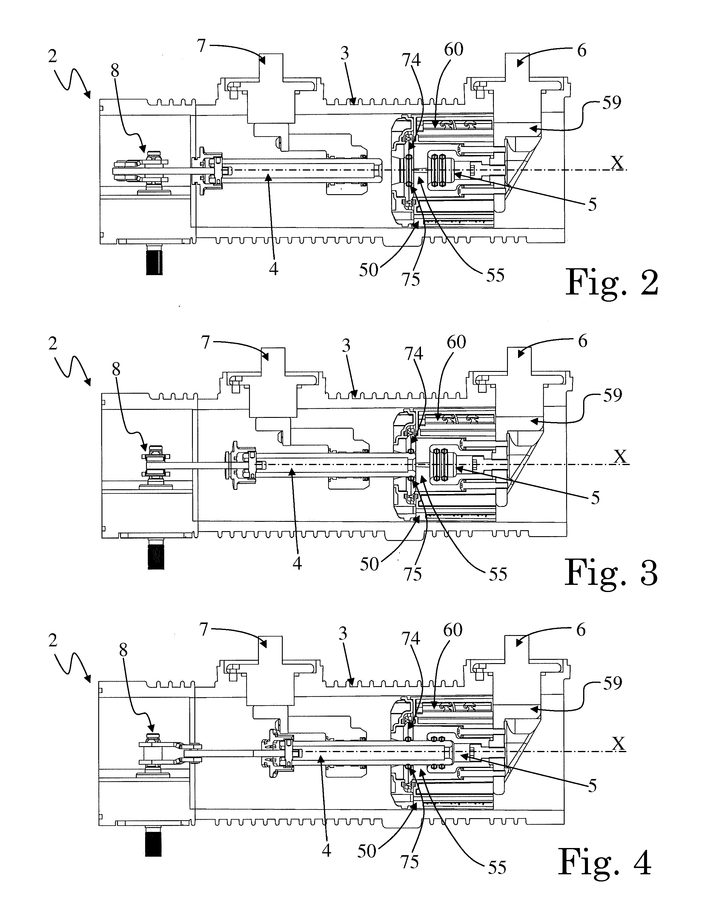
[0021]Exemplary embodiments of the present disclosure include a switching device for connecting / disconnecting a power line to / from at least an associated electrical load, including at least a phase having a housing which houses a movable contact couplable / separable to / from a corresponding fixed contact. The phase includes an electrically semiconducting assembly having an insulating support operatively associated with a plurality of semiconductor devices electrically connected in series to each other, the plurality of semiconductor devices being associated and electrically connected to said fixed contact and to said movable contact, wherein the assembly is configured to be installed into the housing so as to surround at least a portion of at least one of the fixed contact and the movable contact when it is coupled to the fixed contact.

[0022]In the context of the present disclosure, exemplary embodiments will be described by making particular reference to applications connecting / disco...


PUM


Abstract

Exemplary embodiments are directed to a switching device that connects and disconnects a power line to and from, respectively, at least an associated electrical load. The switching device includes at least one phase of the switching device having a housing that includes a movable contact configured to be coupled to and separated from a corresponding fixed contact, wherein the at least one phase of the switching device includes an electrically semiconducting assembly having an insulating support operatively associated with a plurality of semiconductor devices, wherein said plurality of semiconductor devices are connected in series and are electrically connected to said fixed contact and to said movable contact, and wherein said semiconducting assembly is configured to be installed into said housing to surround at least a portion of at least one of said fixed contact and said movable contact when it is coupled to the fixed contact.

Description

RELATED APPLICATION[0001]This application claims priority under 35 U.S.C. §119 to European Patent Application No. 11165428.1 filed in Europe on May 10, 2011, the entire content of which is hereby incorporated by reference in its entirety.FIELD[0002]The present disclosure relates to a switching device for connecting / disconnecting an electrical line to / from at least an associated electrical load, and to a switchgear including such a switching device.BACKGROUND INFORMATION[0003]Switching devices are installed in electrical circuits for connecting / disconnecting a power line to / from one or more associated electrical loads.[0004]Known switching devices can include at least a phase, or pole, with a movable contact which is movable between a first connected position, in which it is coupled to a corresponding fixed contact (closed switching device), and a second separated position, in which it is separated from the fixed contact (open switching device). For example, if the electric load is f...

Claims


Application Information

Patent Timeline
Patent Type & Authority Applications(United States)
IPC IPC(8): H01H33/02
CPCH01H9/56H01H9/542H01H2207/04
Inventor BOFFELLI, CARLOPENZO, ROBERTO
Owner ABB (SCHWEIZ) AG
Learn More