Bipolar ionization device

a technology of ionization device and ionization tube, which is applied in the direction of lighting and heating apparatus, electric supply techniques, corona discharge, etc., can solve the problems of uncontrollable and undesirable ozone, increased energy consumption during the operation of ionization tube, and high replacement cost of such a tub

Active Publication Date: 2012-11-15
GLOBAL PLASMA SOLUTIONS INC
View PDF7 Cites 18 Cited by
  • Summary
  • Abstract
  • Description
  • Claims
  • Application Information

AI Technical Summary

Problems solved by technology

Glass by its very nature has a fragile structure and is prone to breaking The glass tube in an ionization tube also produces a corona discharge, which minimizes the effect of the ionization tube and increases the amount of energy consumed during operation of ionization tube.
The glass tube breaks down over time and must be replaced by the user and the replacement cost for such a tube is high.
Additionally, the glass tube requires a voltage high enough to break down the dielectric strength of the glass, and during the break down process, a corona discharge is created, thus causing uncontrolled and undesirable ozone.

Method used


Image

  • Bipolar ionization device
  • Bipolar ionization device
  • Bipolar ionization device

Examples


Embodiment Construction

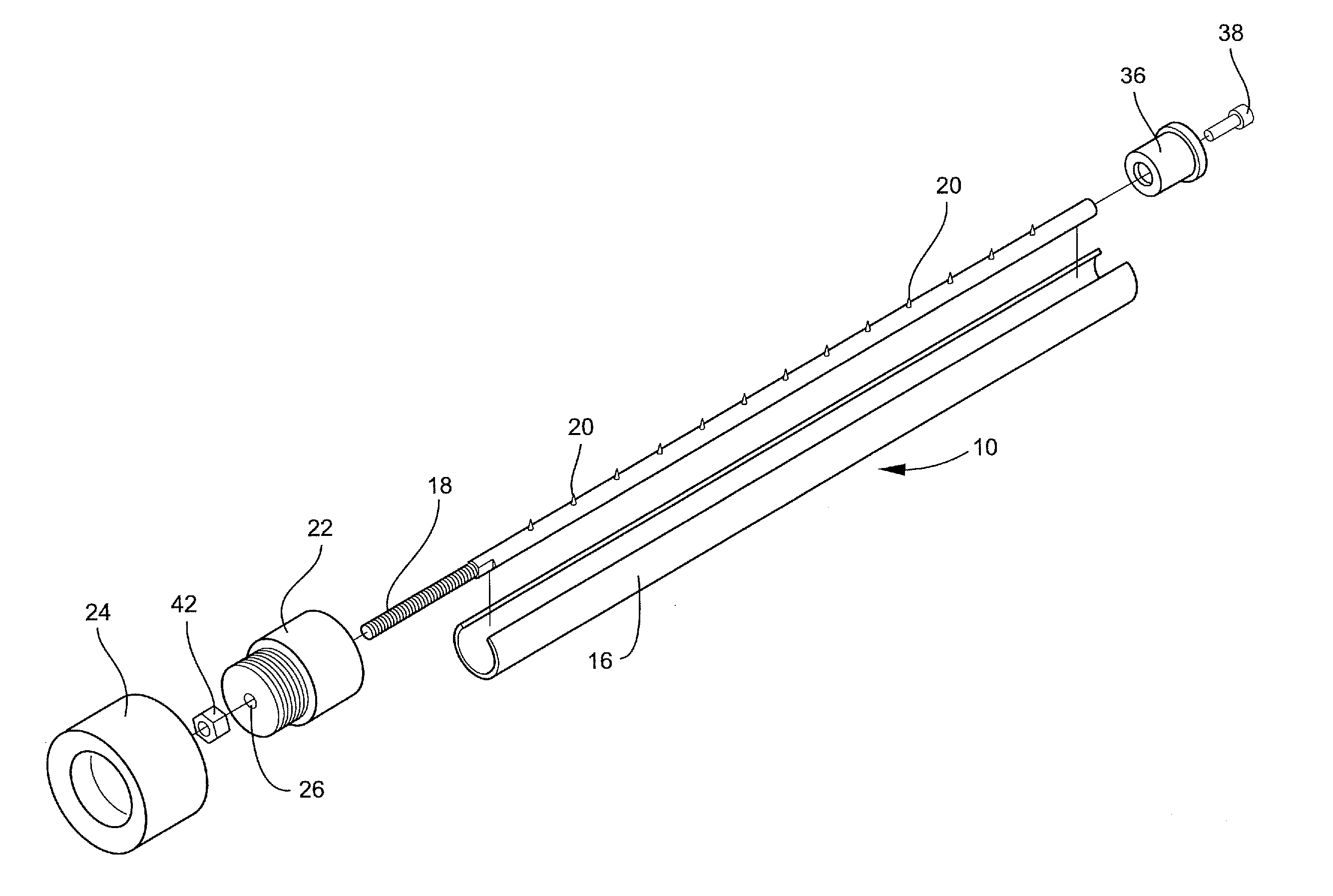
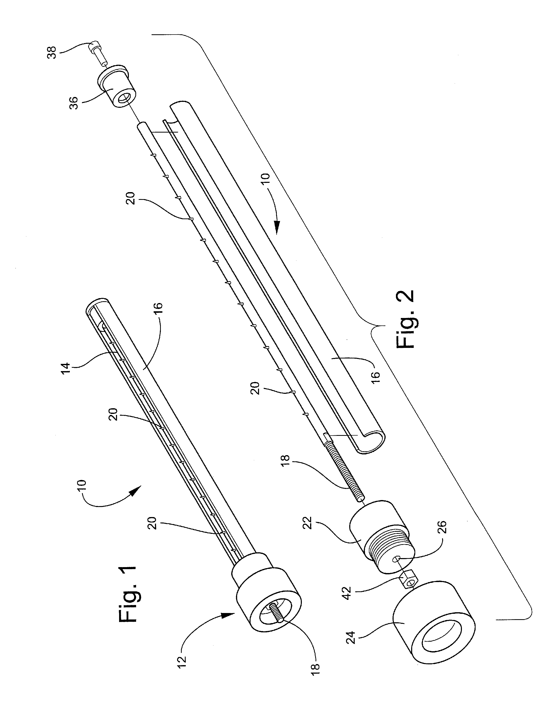
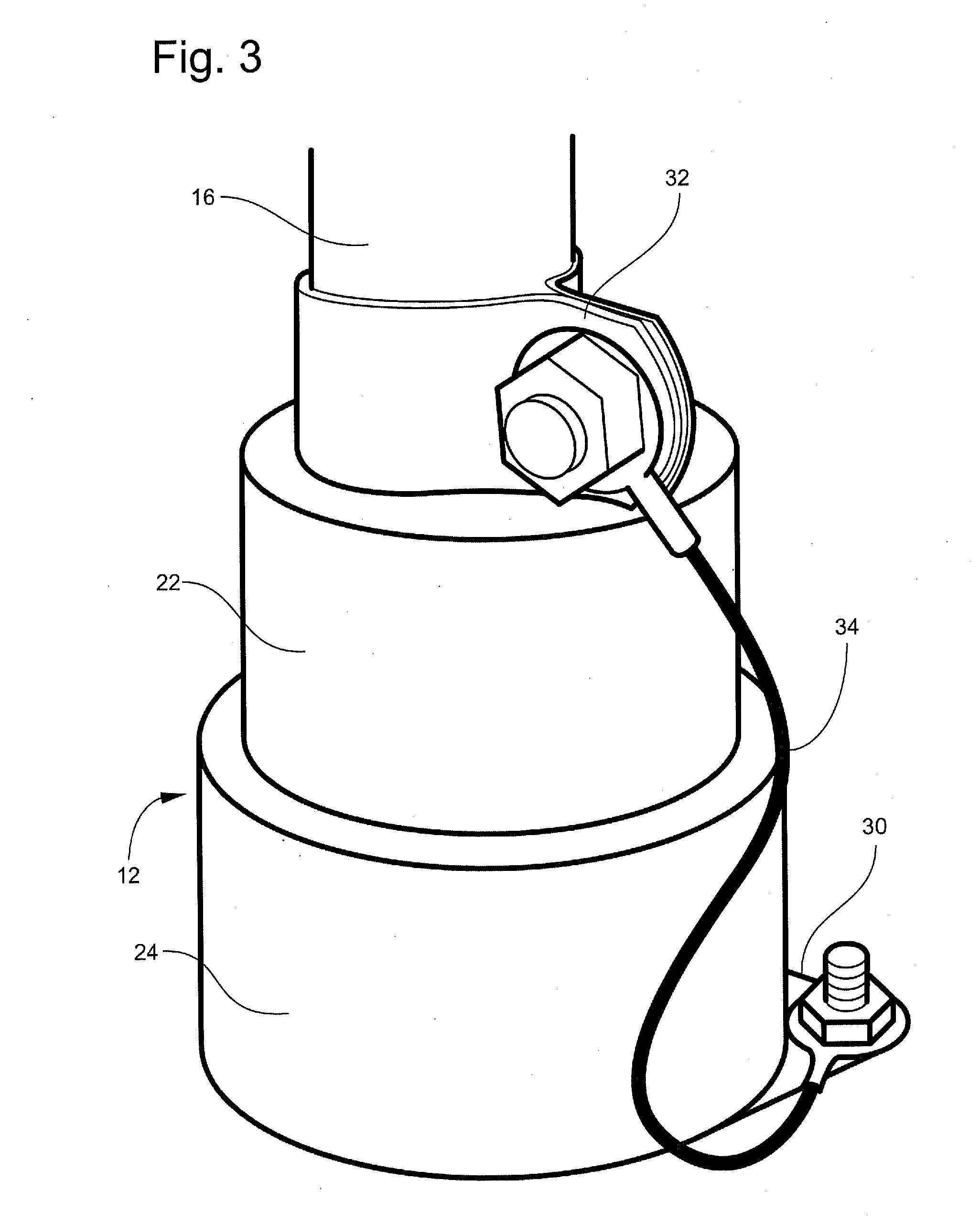
[0026]Referring now specifically to the drawings, a bipolar ionization device is illustrated in FIGS. 1 and 2 and is shown generally at reference numeral 10. The bipolar ionization device 10 generally comprises an electrically insulated base 12, an anode 14, a cathode 16, and a power input terminal 18. The anode 14 is a generally cylindrical tube that extends from the base 12. The cathode 16 is spaced-apart from the anode 14 and partially circumscribes the anode 14. The power input terminal 18 may be integral with the anode 14 or may be engaged to the anode 14. As illustrated in FIG. 1, the power input terminal 18 extends through the base 12 and extends a distance from the base 12 for engaging to a power supply.

[0027]As illustrated in FIG. 2, the power input terminal 18 and the anode 14 are integral, meaning the power input terminal 18 is formed from the anode 14. The power input terminal 18 has a top end and a bottom end and contains threads for receiving corresponding threads of a...


PUM


Abstract

The present invention provides methods and systems for a bipolar ionization device that includes an electrically insulated base, a power input terminal, an anode engaged to the base and the power input terminal, a cathode that partially circumscribes the anode, and plurality of tines extending perpendicularly from the anode having a lower portion and a top portion, wherein the lower portion is engaged to the anode and is wider than the top portion.

Description

CROSS REFERENCE TO RELATED PATENT APPLICATION[0001]The current application claims the benefit of the earlier priority filing date of the provisional application, serial No. 61 / 485,178, that was filed on May 12, 2011.FIELD OF THE INVENTION[0002]The present invention relates generally to a bipolar ionization device and more generally relates to a bipolar ionization device that includes an anode that is partially circumscribed by a cathode.BACKGROUND OF THE INVENTION[0003]Current ionization tubes utilize a cathode that is completely surrounded by a glass tube. The inside of the glass tube contains a wire mesh that serves as an anode. Glass by its very nature has a fragile structure and is prone to breaking The glass tube in an ionization tube also produces a corona discharge, which minimizes the effect of the ionization tube and increases the amount of energy consumed during operation of ionization tube. The glass tube breaks down over time and must be replaced by the user and the repl...

Claims


Application Information

Patent Timeline
Patent Type & Authority Applications(United States)
IPC IPC(8): H01T23/00
CPCB03C3/383B03C3/41B03C3/70B03C3/86B03C2201/08H01T23/00A61L2/14F26B21/003A61L9/22A61L2209/16H01T19/04B03C2201/10
Inventor WADDELL, CHARLES HOUSTONCHRISTIANSEN, JOSEPH ANTON
Owner GLOBAL PLASMA SOLUTIONS INC
Why Eureka
Try Eureka