Solar heat receiver

a heat receiver and solar energy technology, applied in solar heat storage, lighting and heating apparatus, collector casings, etc., can solve the problems of difficult to expect a high temperature rise of the thermal medium, power generation is not sufficiently propagated, and the effect of low effective energy over a wide rang

Inactive Publication Date: 2012-11-22
MITSUBISHI HEAVY IND LTD
View PDF26 Cites 8 Cited by
  • Summary
  • Abstract
  • Description
  • Claims
  • Application Information

AI Technical Summary

Benefits of technology

[0022]According to the solar heat receiver of the present invention, the temperature difference between the front portion and th

Problems solved by technology

However, with regard to energy distribution of clean energy, effective energy (energy that may be externally taken and utilized) over a wide range is low.
Due to this situation, since the power generation using clean energy has low conversion efficiency to power and high cost of power generation, such a

Method used


Image

  • Solar heat receiver
  • Solar heat receiver
  • Solar heat receiver

Examples


first embodiment

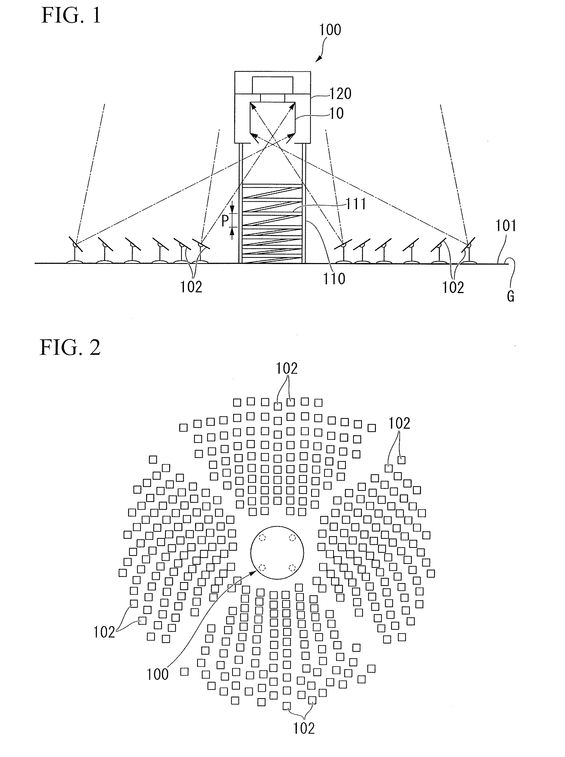
[0035]A tower type solar power plant shown in FIG. 1 includes a solar light heat receiver placed on a high tower, and mirrors called heliostats which are placed on the ground around the solar light heat receiver and are able to control reflected light. The tower type solar power plant condenses sunlight on the solar light heat receiver on the tower through the heliostats to generate electricity.

[0036]As shown in FIG. 1, a heliostat field 101 is provided on the ground G. A plurality of heliostats 102 for reflecting sunlight are placed in the heliostat field 101. Furthermore, a tower type solar light condensation heat receiver 100 which receives sunlight guided by the heliostats 102 is provided in a central section of the heliostat field 101. As shown in FIG. 2, the heliostats 102 are placed 360° around the entire circumference of the tower type solar light condensation heat receiver 100.

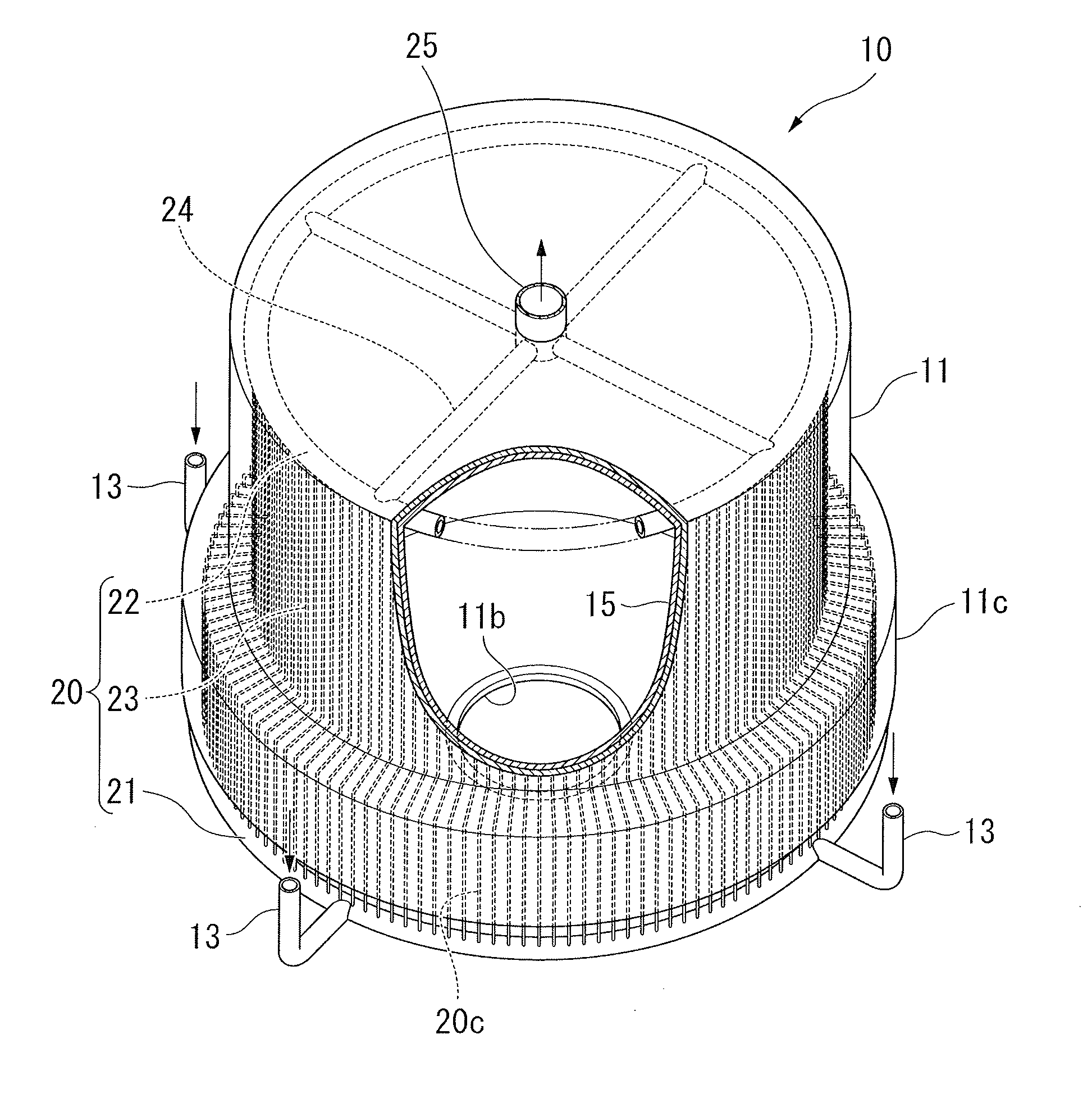
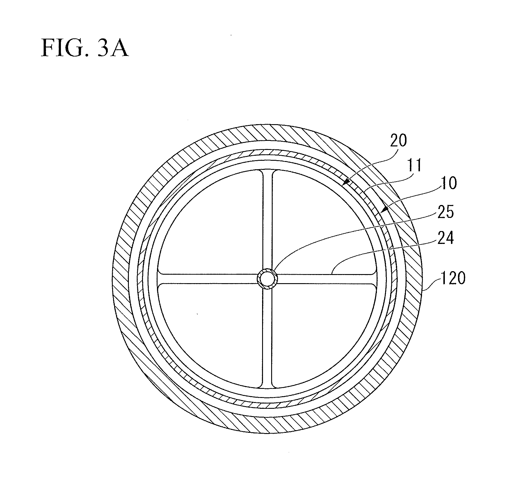
[0037]The tower type solar light condensation heat receiver 100 is constituted by a tower 110 erec...

second embodiment

[0063]As shown in FIG. 10, a heat receiver (a solar heat receiver) 10A according to a second embodiment is configured so that a pipe diameter of an expanded section 20e in the heat-receiving pipe main bodies 23 included in the heat-receiving pipe 20 is greater than that of a portion other than the expanded section 20e. That is, in a region in which the diameter of the circle passing through the center of each heat-receiving pipe main body 23 is expanded, the diameter of each heat-receiving pipe main body 23 is expanded compared to the diameter of each heat-receiving pipe main body 23 in other regions.

[0064]In this manner, by increasing the diameter of the expanded section 20e of the heat-receiving pipe main bodies 23 included in the heat-receiving pipe 20, the surface area of the outer circumferential surface of the heat-receiving pipe 20 is further increased, and thus the heat input quantity per unit area may be further reduced. Furthermore, by enlarging the diameter of the heat-re...


PUM


Abstract

Heat-receiving pipes of a heat receiver have portions having high heat flux on at the side near an opening in a length direction and extending to positions outside of a casing in a radial direction. Expanded sections having an expanded pitch circle diameter constituted by the plurality of heat-receiving pipes are formed, and a heat input quantity per unit area of the heat-receiving pipe is decreased in the portions near the opening.

Description

FIELD OF THE INVENTION[0001]The present invention relates to a solar heat receiver for increasing a temperature of a fluid medium that drives a turbine of a solar heat power generator.BACKGROUND ART[0002]In recent years, in terms of prevention of global warming and suppression of the use of fossil fuels, power generation using clean energy such as natural energy having less harmful emissions such as carbon dioxide and nitrogen oxides, and recycled energy reusing the resources has received attention. The clean energy exceeds a certain amount of electrical energy required by the whole world. However, with regard to energy distribution of clean energy, effective energy (energy that may be externally taken and utilized) over a wide range is low. Due to this situation, since the power generation using clean energy has low conversion efficiency to power and high cost of power generation, such a power generation has not been sufficiently propagated. Thus, as the power generation type, powe...

Claims


Application Information

Patent Timeline
IPC IPC(8): F24J2/24F24J2/46F24S10/70F24S20/20
CPCF24J2/07F24J2/248F24J2/464Y02E10/44F24J2/34Y02E10/41F24S10/748F24S20/20F24S60/00F24S80/40Y02E10/40
Inventor ATARASHIYA, KENJIHORIE, SHIGENARIMIZUTA, KEIJIMAEDA, MANABUKOBAYASHI, KAZUTA
Owner MITSUBISHI HEAVY IND LTD
Why Eureka
Try Eureka